
Hongxing Yang, Haijin Fu, Pengcheng Hu, Ruitao Yang, Xu Xing, Liang Yu, Di Chang, Jiubin Tan. Ultra-Precision and High-Speed Laser Interferometric Displacement Measurement Technology and Instrument[J]. Laser & Optoelectronics Progress, 2022, 59(9): 0922018
- Laser & Optoelectronics Progress
- Vol. 59, Issue 9, 0922018 (2022)
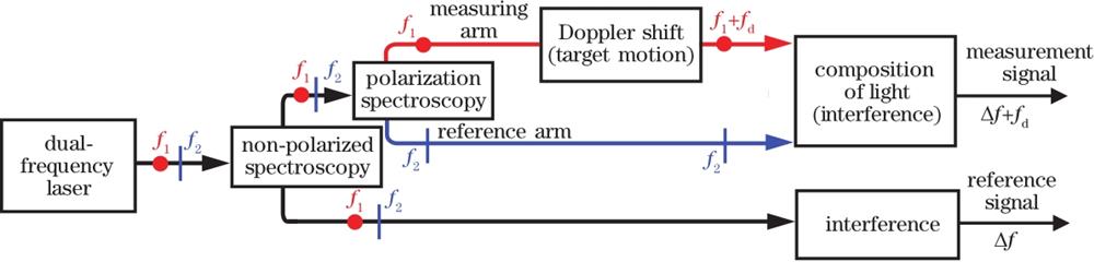
Fig. 1. Basic principle diagram of coaxial beams based dual-frequency laser interferometer
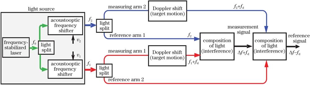
Fig. 2. Basic principle diagram of spatially separated beams based laser interferometer
Fig. 3. Schematic diagram and effect of high precision laser frequency stabilization method based on offset correction of frequency stabilization point. (a) Principle of double longitudinal mode thermal frequency stabilization; (b) comparison of relative frequency accuracy; (c) frequency accuracy calibration certificate
Fig. 4. Schematic diagram and effect of laser frequency stabilization method based on correction of frequency stabilization point and weakly coupled water cooling structure. (a) Principle of frequency stabilization; (b) comparison of frequency stabilization effect
Fig. 5. Schematic diagram and effect of laser frequency stabilization method based on frequency offset locking of iodine molecular optical frequency standard and weakly coupled water cooling structure. (a) Principle of frequency stabilization; (b) frequency accuracy calibration certificate
Fig. 6. Frequency difference stabilization of Zeeman laser
Fig. 7. Zeeman frequency stabilized laser
Fig. 8. Structural drawing and frequency difference stability of dual-frequency laser source based on dual-acousto-optic modulation. (a) Structural drawing; (b) frequency difference stability
Fig. 9. Photos of dual-frequency lasers based on dual-acousto-optic modulation. (a) Spatial separation type; (b) integrated water cooling type; (c) frequency offset locking type
Fig. 10. Schematic diagram and frequency difference stability of dual-light source locked dual-frequency laser. (a) Schematic diagram; (b) frequency difference stability
Fig. 11. Self-developed interferometer group with multi-axis based on coaxial beams. (a) 3D design drawing of typical interferometer group; (b) photo of multi-axis interferometer group
Fig. 12. Self-developed interferometer group with multi-axis based on non-coaxial beams. (a) 3D design drawing of typical interferometer group; (b) photo of multi-axis interferometer group
Fig. 13. Schematic diagram of phase measurement method based on phase locked loop frequency doubling and digital delay subdivision[26]
Fig. 14. Signal processing card based on time difference measurement and test results. (a) Signal processing card; (b) experimental results of displacement resolution
Fig. 15. Schematic diagram of high speed and high resolution interference signal processing method based on dynamic quadrature phase locking[27]. (a) Schematic diagram of phase measuring system structure; (b) comparison of measurement models; (c) comparison of measurement characteristics
Fig. 16. High-speed and high-resolution interference signal processing card based on dynamic quadrature phase locking. (a) Photo of signal processing card; (b) static displacement measurement data; (c) dynamic measurement standard deviation
Fig. 17. Photos of self-developed series ultra-precision high-speed laser interferometers. (a) Ultra-precision high-speed laser interferometer with more than 20 axes; (b) uniaxial sub-nanometer laser interferometer; (c) triaxial sub-nanometer laser interferometer
Fig. 18. Schematic diagram of application of ultra-precision high-speed laser interferometry system in lithography machine and field photo
Fig. 19. National quantized mass standard and integrated sub-nanometer interferometer
|
Table 1. Internal measurement error analysis of coaxial beams based dual-frequency laser interferometer
|
Table 2. Self-developed ultra-precision high-speed laser interferometer products and their main parameters

Set citation alerts for the article
Please enter your email address
© Copyright 2018-2021 | Chinese Laser Press. All Rights Reserved 沪ICP备15018463号-20