• Journal of Semiconductors
  • Vol. 40, Issue 10, 101306 (2019)
Cheng Wang1 and Yueguang Zhou1、2、3
Author Affiliations
  • 1School of Information Science and Technology, ShanghaiTech University, Shanghai 201210, China
  • 2Shanghai Institute of Microsystem and Information Technology, Chinese Academy of Sciences, Shanghai 200050, China
  • 3University of Chinese Academy of Sciences, Beijing 100049, China
  • show less
    DOI: 10.1088/1674-4926/40/10/101306 Cite this Article
    Cheng Wang, Yueguang Zhou. Dynamics of InAs/GaAs quantum dot lasers epitaxially grown on Ge or Si substrate[J]. Journal of Semiconductors, 2019, 40(10): 101306 Copy Citation Text show less
    (Color online) Nonradiative recombination effects on the threshold current and the carrier numbers in GS, ES, and RS at the threshold, respectively.
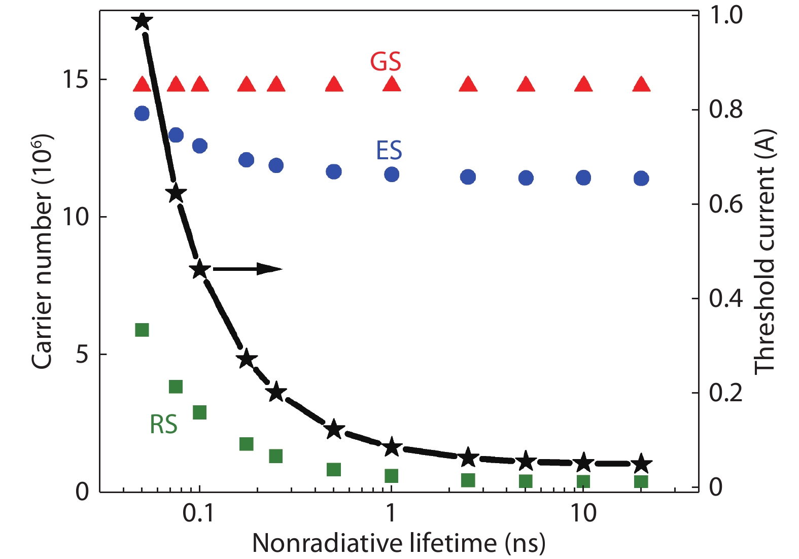
    Fig. 1. (Color online) Nonradiative recombination effects on the threshold current and the carrier numbers in GS, ES, and RS at the threshold, respectively.
    (Color online) Nonradiative recombination effects on the LBF. (Reproduced from Ref. [43].)
    Fig. 2. (Color online) Nonradiative recombination effects on the LBF. (Reproduced from Ref. [43].)
    (Color online) Non-radiative recombination effects on (a) the RIN spectrum, (b) the FN spectrum, and (c) the low-frequency RIN and the peak FN.
    Fig. 3. (Color online) Non-radiative recombination effects on (a) the RIN spectrum, (b) the FN spectrum, and (c) the low-frequency RIN and the peak FN.
    (Color online) Non-radiative recombination effects on (a) the intensity modulation response, and (b) the 3-dB modulation bandwidth and the damping factor.
    Fig. 4. (Color online) Non-radiative recombination effects on (a) the intensity modulation response, and (b) the 3-dB modulation bandwidth and the damping factor.
    (Color online) Non-radiative recombination effects on the critical feedback level. (Reproduced from Ref. [43].)
    Fig. 5. (Color online) Non-radiative recombination effects on the critical feedback level. (Reproduced from Ref. [43].)
    (Color online) Sub-threshold LBF of Ge-based Qdot lasers with a cavity length of (a) 4.4 mm and (b) 2.2 mm. Both lasers have a ridge width of 4.0 μm, and a lasing threshold of 60 mA.
    Fig. 6. (Color online) Sub-threshold LBF of Ge-based Qdot lasers with a cavity length of (a) 4.4 mm and (b) 2.2 mm. Both lasers have a ridge width of 4.0 μm, and a lasing threshold of 60 mA.
    (Color online) LBFs of Si-based undoped (closed circle) and p-doped (triangle) Qdot lasers. (Reproduced from Ref. [55].)
    Fig. 7. (Color online) LBFs of Si-based undoped (closed circle) and p-doped (triangle) Qdot lasers. (Reproduced from Ref. [55].)
    (Color online) RINs of (a) Ge-based Qdot laser (Ith = 300 mA), and (b) GaAs-based Qdot laser (Ith = 120 mA). (Reproduced from Ref. [58].)
    Fig. 8. (Color online) RINs of (a) Ge-based Qdot laser (Ith = 300 mA), and (b) GaAs-based Qdot laser (Ith = 120 mA). (Reproduced from Ref. [58].)
    (Color online) Optical feedback effects on the normalized intensity noise power of (a) Ge-based laser (Ith = 75 mA), and (b) GaAs-based laser (Ith = 60 mA), with respect to the free-running cases. The noise power is averaged in the frequency range of 10–100 MHz. (Reproduced from Ref. [43].)
    Fig. 9. (Color online) Optical feedback effects on the normalized intensity noise power of (a) Ge-based laser (Ith = 75 mA), and (b) GaAs-based laser (Ith = 60 mA), with respect to the free-running cases. The noise power is averaged in the frequency range of 10–100 MHz. (Reproduced from Ref. [43].)
    (Color online) Effects of optical feedback on RINs of (a) a Qdot laser epitaxially grown on Si (Ith = 38 mA), and of (b) a Qwell laser heterogeneously integrated on Si (Ith = 32 mA). (Reproduced from Ref. [61].)
    Fig. 10. (Color online) Effects of optical feedback on RINs of (a) a Qdot laser epitaxially grown on Si (Ith = 38 mA), and of (b) a Qwell laser heterogeneously integrated on Si (Ith = 32 mA). (Reproduced from Ref. [61].)
    (Color online) Optical feedback effects on (a, b) the optical power distribution of two cavity modes, and (c, d) on the electrical power distribution. (a) and (c) are for a Si-based Qdot laser (Ith = 26.5 mA), (b) and (d) are for a InP-based Qwell laser (Ith = 28 mA). (Reproduced from Ref. [63].)
    Fig. 11. (Color online) Optical feedback effects on (a, b) the optical power distribution of two cavity modes, and (c, d) on the electrical power distribution. (a) and (c) are for a Si-based Qdot laser (Ith = 26.5 mA), (b) and (d) are for a InP-based Qwell laser (Ith = 28 mA). (Reproduced from Ref. [63].)
    (Color online) Intensity modulation responses of two Si-based Qdot lasers. The threshold current of device 1 is 18.9 mA, and is 19.1 mA for device 2. The cavity length is 2.5 mm. (Reproduced from Ref. [70].)
    Fig. 12. (Color online) Intensity modulation responses of two Si-based Qdot lasers. The threshold current of device 1 is 18.9 mA, and is 19.1 mA for device 2. The cavity length is 2.5 mm. (Reproduced from Ref. [70].)
    (Color online) Intensity modulation responses of (a) undoped and (b) p-doped Qdot lasers on Si. (c) Eye diagrams of the p-doped laser, under non-return-to-zero modulation. The cavity length is 0.58 mm. (Reproduced from Ref. [71].)
    Fig. 13. (Color online) Intensity modulation responses of (a) undoped and (b) p-doped Qdot lasers on Si. (c) Eye diagrams of the p-doped laser, under non-return-to-zero modulation. The cavity length is 0.58 mm. (Reproduced from Ref. [71].)
    (Color online) (a) Schematic structure of a mode-locked Qdot laser on Si with a repetition rate of 9.0 GHz. (b) SNR of the fundamental RF peak. (c) Mode-locking pulse width as functions of forward bias current and reverse bias voltage. The threshold current is 90 mA without biasing the absorber section. (Reproduced from Ref. [73].)
    Fig. 14. (Color online) (a) Schematic structure of a mode-locked Qdot laser on Si with a repetition rate of 9.0 GHz. (b) SNR of the fundamental RF peak. (c) Mode-locking pulse width as functions of forward bias current and reverse bias voltage. The threshold current is 90 mA without biasing the absorber section. (Reproduced from Ref. [73].)
    (Color online) Si-based mode-locked Qdot laser with a repetition rate of 20 GHz. (a) Autocorrelation pulse shape. (b) RF spectrum. (c) RF lineshape. (d) Single-sideband phase noise. The threshold current is 42 mA without biasing the absorber section. (Reproduced from Ref. [79].)
    Fig. 15. (Color online) Si-based mode-locked Qdot laser with a repetition rate of 20 GHz. (a) Autocorrelation pulse shape. (b) RF spectrum. (c) RF lineshape. (d) Single-sideband phase noise. The threshold current is 42 mA without biasing the absorber section. (Reproduced from Ref. [79].)
    SymbolDescriptionValue
    RS to ES capture time6.3 ps
    ES to GS relaxation time2.9 ps
    ES to RS escape time2.7 ns
    GS to ES escape time10.4 ps
    RS spontaneous emission time0.5 ns
    ES spontaneous emission time0.5 ns
    GS spontaneous emission time1.2 ns
    Photon lifetime4.1 ps
    Polarization dephasing time0.1 ps
    Spontaneous emission factor1.0 × 10–4
    GS differential gain5.0 × 10–15 cm2
    ES differential gain10 × 10–15 cm2
    RS differential gain2.5 × 10–15 cm2
    Gain compression factor2.0 × 10–16 cm3
    Optical confinement factor0.06
    GS contribution to LBF0.50
    Total dot number107
    Total RS state number4.8 × 106
    Active region volume5.0 × 10–11 cm3
    RS region volume1.0 × 10–16 cm3
    Table 1. Qdot laser parameters used for the simulation.
    Cheng Wang, Yueguang Zhou. Dynamics of InAs/GaAs quantum dot lasers epitaxially grown on Ge or Si substrate[J]. Journal of Semiconductors, 2019, 40(10): 101306
    Download Citation