
Yaqian Qian, Shushan Qiao, Rongqiang Yang. Variation tolerance for high-speed negative capacitance FinFET SRAM bit cell[J]. Journal of Semiconductors, 2020, 41(6): 062403
- Journal of Semiconductors
- Vol. 41, Issue 6, 062403 (2020)
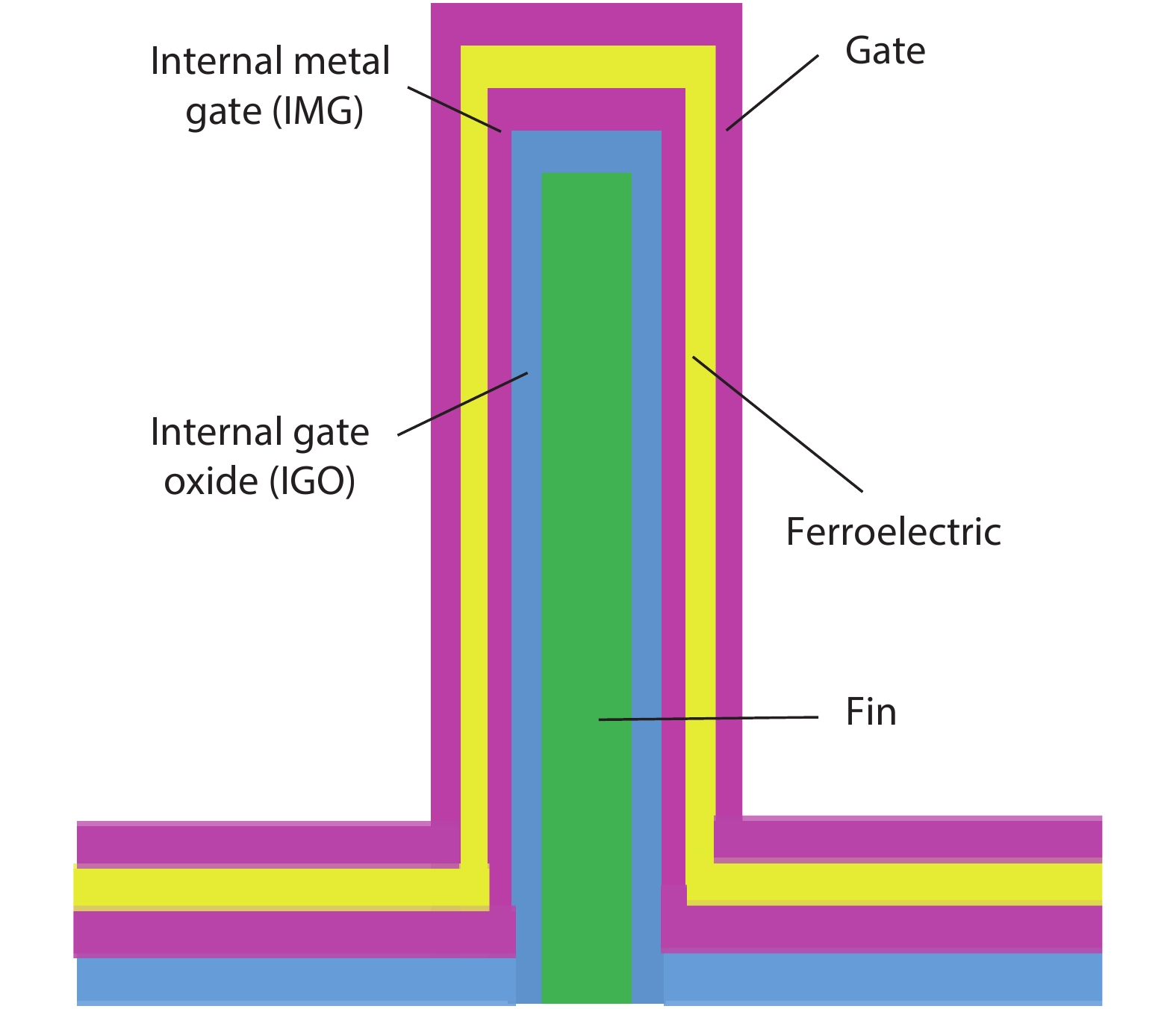
Fig. 1. (Color online) the structure of NC-FinFET.
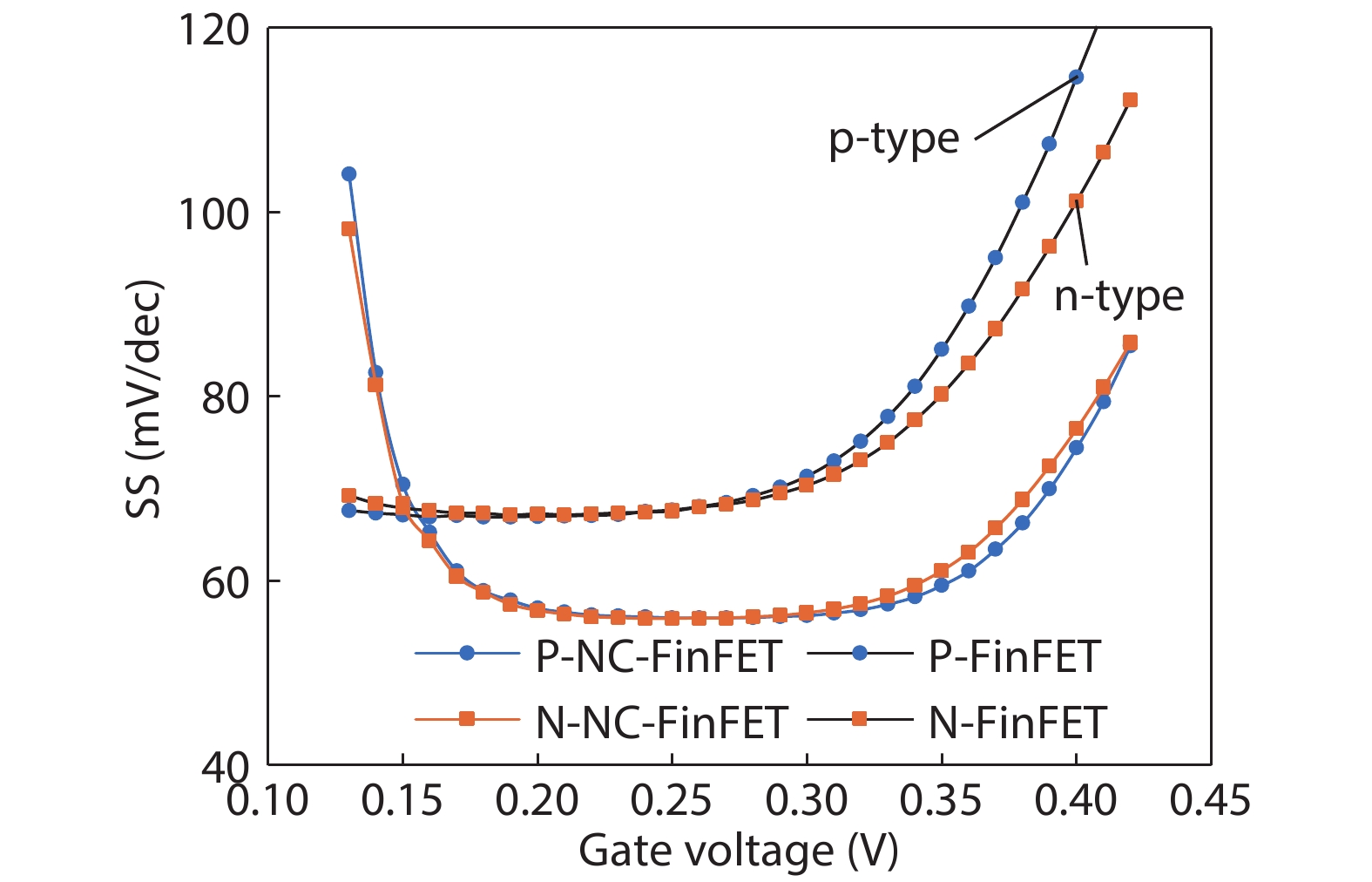
Fig. 2. (Color online) The subthreshold swing improved by NC compared to the baseline.
Fig. 3. The schematic of traditional 6T SRAM-cell.
Fig. 4. The simulation flow chart for analysis the performance variation for the 6T SRAM, and the compact model is the BSIM-CMG cooperating L-K equations.
Fig. 5. (Color online) The V T mismatch between n-type and p-type NC-FinFET under the same process: when the thickness of ferroelectric material increases, the mismatch gets worse.
Fig. 6. (Color online) (a) Read speed, (b) leakage, (c) SNM, and (d) WM of NC-FinFET SRAM influenced by the thickness of ferroelectric material.
Fig. 7. (Color online) (a) Read speed, (b) leakage, (c) SNM, and (d) WM of NC-FinFET SRAM influenced by the fin number of baseline with fixed FE thickness 3 nm.
Fig. 8. (Color online) (a) Read speed, (b) leakage, (c) SNM, and (d) WM of NC-FinFET SRAM influenced by the channel length of baseline with one fin.
Fig. 9. (Color online) (a) Read speed, (b) leakage, (c) SNM, and (d) WM of NC-FinFET SRAM influenced by temperature with one fin and supply voltage ranges from 0.5 to 0.7 V.

Set citation alerts for the article
Please enter your email address
© Copyright 2018-2021 | Chinese Laser Press. All Rights Reserved 沪ICP备15018463号-20