• Laser & Optoelectronics Progress
  • Vol. 57, Issue 20, 200001 (2020)
Kai Wen1, Ying Ma1, Meiling Zhang1, Yu Wang1, Chi Fu1, Juanjuan Zheng1, Lixin Liu1, Peng Gao1、*, and Baoli Yao2
Author Affiliations
  • 1School of Physics and Optoelectronic Engineering, Xidian University, Xi'an, Shaanxi 710071, China
  • 2State Key Laboratory of Transient Optics and Photonics, Xi'an Institute of Optics and Precision Mechanics, Chinese Academy of Sciences, Xi'an, Shaanxi 710119, China
  • show less
    DOI: 10.3788/LOP57.200001 Cite this Article Set citation alerts
    Kai Wen, Ying Ma, Meiling Zhang, Yu Wang, Chi Fu, Juanjuan Zheng, Lixin Liu, Peng Gao, Baoli Yao. Quantitative Phase Microscopy with High Stability[J]. Laser & Optoelectronics Progress, 2020, 57(20): 200001 Copy Citation Text show less
    Measurement of 3D profile and refractive index via phase imaging
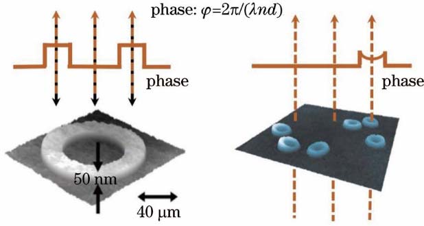
    Fig. 1. Measurement of 3D profile and refractive index via phase imaging
    Schematic of DHM optical path. (a) Imaging principle of DHM; (b) interference pattern of object light and reference light
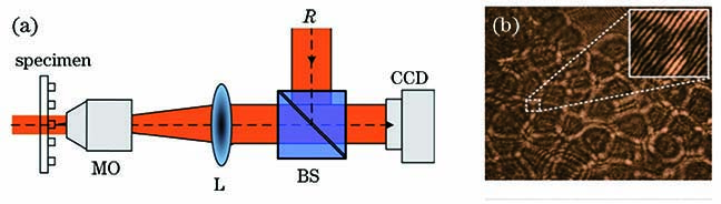
    Fig. 2. Schematic of DHM optical path. (a) Imaging principle of DHM; (b) interference pattern of object light and reference light
    Reconstruction results of DHM. (a) Reconstructed amplitude; (b) reconstructed phase
    Fig. 3. Reconstruction results of DHM. (a) Reconstructed amplitude; (b) reconstructed phase
    Common-path interference microscopy. (a) Fizeau interference microscopy; (b) Mirau interference microscopy
    Fig. 4. Common-path interference microscopy. (a) Fizeau interference microscopy; (b) Mirau interference microscopy
    Off-axis point-diffraction digital holographic microscopy[57]. G, grating; IP, image plane; L1-L2, lenses (f1 and f2 are focal distances of L1 and L2, respectively); SF, spatial filter (expanded in the inset); VPS, virtual source point
    Fig. 5. Off-axis point-diffraction digital holographic microscopy[57]. G, grating; IP, image plane; L1-L2, lenses (f1 and f2 are focal distances of L1 and L2, respectively); SF, spatial filter (expanded in the inset); VPS, virtual source point
    Imaging results of off-axis point-diffraction DHM[57]. (a) Quantitative phase image of whole blood smear; (b) temporal fluctuations of the spatial standard deviation of the field of view without sample and arbitrary single point in the field of view. σ is the temporal standard deviation for these two signals
    Fig. 6. Imaging results of off-axis point-diffraction DHM[57]. (a) Quantitative phase image of whole blood smear; (b) temporal fluctuations of the spatial standard deviation of the field of view without sample and arbitrary single point in the field of view. σ is the temporal standard deviation for these two signals
    Optical path for phase-shifting point-diffraction DHM with common-path and in-line configuration based on diffraction grating[61]. G1 and G2, Ronchi phase grating; L1--L6, lens; MO1 and MO2, objective; P, polarizer combination; P1--P3, polarizer combination; PH, pinhole filter
    Fig. 7. Optical path for phase-shifting point-diffraction DHM with common-path and in-line configuration based on diffraction grating[61]. G1 and G2, Ronchi phase grating; L1--L6, lens; MO1 and MO2, objective; P, polarizer combination; P1--P3, polarizer combination; PH, pinhole filter
    Holographic patterns and reconstructed result obtained with coaxial phase shifting point-diffraction DHM[61]. (a)--(d) Holographic patterns with phase shifts of 0, π/2, π, and 3π/2; (e) reconstructed phase
    Fig. 8. Holographic patterns and reconstructed result obtained with coaxial phase shifting point-diffraction DHM[61]. (a)--(d) Holographic patterns with phase shifts of 0, π/2, π, and 3π/2; (e) reconstructed phase
    SLM based common-path phase-shifting digital holographic microscopy[63]. (a) On-axis illumination; (b) off-axis illumination
    Fig. 9. SLM based common-path phase-shifting digital holographic microscopy[63]. (a) On-axis illumination; (b) off-axis illumination
    Experimental setup of SMIM[64]
    Fig. 10. Experimental setup of SMIM[64]
    Diagram of single-beam in-line digital holographic microscopy[90]
    Fig. 11. Diagram of single-beam in-line digital holographic microscopy[90]
    Experimental hologram and reconstruction results[90]. (a) Reconstructed result of conventional back propagation algorithm (with twin image); (b) reconstructed result after 500 iterations by CS algorithm (without twin image); (c)(d) enlarged areas of the dotted box in Figs. 12 (a) and (b), respectively
    Fig. 12. Experimental hologram and reconstruction results[90]. (a) Reconstructed result of conventional back propagation algorithm (with twin image); (b) reconstructed result after 500 iterations by CS algorithm (without twin image); (c)(d) enlarged areas of the dotted box in Figs. 12 (a) and (b), respectively
    Quantitative phase contrast microscopy with parallel light illumination[92]
    Fig. 13. Quantitative phase contrast microscopy with parallel light illumination[92]
    Diagram of phase contrast microscopy optical path based on SLM[82]. (a) Surrounding grating; (b) center grating; (c)--(e) phase shift interferograms with phase shifts between the diffracted and undiffracted parts of 0, π/2, and π, respectively
    Fig. 14. Diagram of phase contrast microscopy optical path based on SLM[82]. (a) Surrounding grating; (b) center grating; (c)--(e) phase shift interferograms with phase shifts between the diffracted and undiffracted parts of 0, π/2, and π, respectively
    Quantitative phase contrast microscopy based on polarization modulation[96]
    Fig. 15. Quantitative phase contrast microscopy based on polarization modulation[96]
    Measurement results of airflow based on quantitative phase contrast microscopy with polarization modulation[96]. (a) Four-step phase-shift interference patterns of airflow; (b) reconstructed phase distribution of airflow
    Fig. 16. Measurement results of airflow based on quantitative phase contrast microscopy with polarization modulation[96]. (a) Four-step phase-shift interference patterns of airflow; (b) reconstructed phase distribution of airflow
    Setup of UO-QPM and reconstruction results[101]. (a) Schematic of UO-QPM system; (b) reconstruction result of cos7 cells
    Fig. 17. Setup of UO-QPM and reconstruction results[101]. (a) Schematic of UO-QPM system; (b) reconstruction result of cos7 cells
    Diagram of optical path of improved Zernike phase contrast imaging[84]
    Fig. 18. Diagram of optical path of improved Zernike phase contrast imaging[84]
    Imaging results of microlens array based on quantitative phase contrast microscopy with multi-point off-axis illumination[84]. (a)--(c) Interference patterns with phase shifts of 0, -π/2, and π/2, respectively; (d) reconstructed phase distribution of microlens arrays
    Fig. 19. Imaging results of microlens array based on quantitative phase contrast microscopy with multi-point off-axis illumination[84]. (a)--(c) Interference patterns with phase shifts of 0, -π/2, and π/2, respectively; (d) reconstructed phase distribution of microlens arrays
    Kai Wen, Ying Ma, Meiling Zhang, Yu Wang, Chi Fu, Juanjuan Zheng, Lixin Liu, Peng Gao, Baoli Yao. Quantitative Phase Microscopy with High Stability[J]. Laser & Optoelectronics Progress, 2020, 57(20): 200001
    Download Citation