• Laser & Optoelectronics Progress
  • Vol. 59, Issue 9, 0922009 (2022)
Miao Yuan, Yiyu Sun, and Yanqiu Li*
Author Affiliations
  • School of Optics and Photonics, Beijing Institute of Technology, Beijing 100081, China
  • show less
    DOI: 10.3788/LOP202259.0922009 Cite this Article Set citation alerts
    Miao Yuan, Yiyu Sun, Yanqiu Li. Advanced Computational Lithography[J]. Laser & Optoelectronics Progress, 2022, 59(9): 0922009 Copy Citation Text show less
    Flow of computational lithography
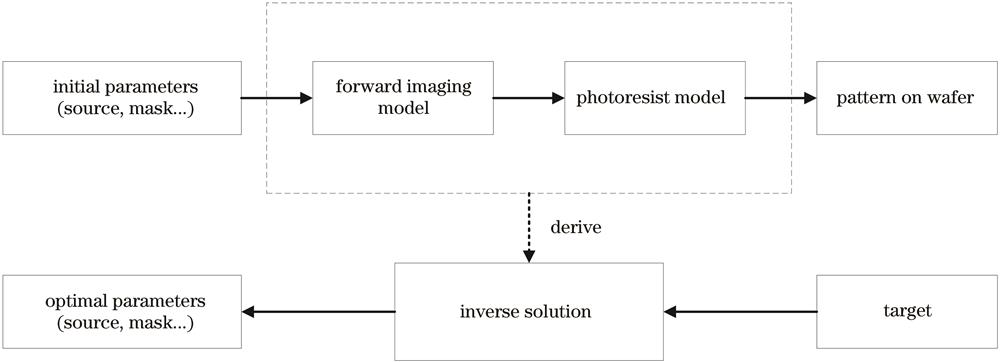
    Fig. 1. Flow of computational lithography
    Imaging formation based on the vector imaging model[32]
    Fig. 2. Imaging formation based on the vector imaging model[32]
    Process window for the initial source and mask, OPC algorithm, and HSMO algorithm[16]. (a) Isolate line-space pattern; (b) semi-dense line-space pattern; (c) dense contact holes
    Fig. 3. Process window for the initial source and mask, OPC algorithm, and HSMO algorithm[16]. (a) Isolate line-space pattern; (b) semi-dense line-space pattern; (c) dense contact holes
    Process window of conventional SMO and the ELASMO[60]
    Fig. 4. Process window of conventional SMO and the ELASMO[60]
    The convergence curves of IHTs SMO and Newton-IHTs SMO[90]
    Fig. 5. The convergence curves of IHTs SMO and Newton-IHTs SMO[90]
    Pattern error comparison of full-chip SO method simulation[92]
    Fig. 6. Pattern error comparison of full-chip SO method simulation[92]
    Comparison of pattern errors of SMO results between traditional imaging model and IPSF model[93]
    Fig. 7. Comparison of pattern errors of SMO results between traditional imaging model and IPSF model[93]
    Optimization results and evaluations of the proposed LASSMO only considering c8[105]
    Fig. 8. Optimization results and evaluations of the proposed LASSMO only considering c8[105]
    Principle of the FlexWave manipulator[113]
    Fig. 9. Principle of the FlexWave manipulator[113]
    Schematic diagram of the PWO method to compensate for TMIA[19]
    Fig. 10. Schematic diagram of the PWO method to compensate for TMIA[19]
    Pupil for different methods[124]. (a) Scalar pupil for PWO method; (b) vector pupil for VPO method
    Fig. 11. Pupil for different methods[124]. (a) Scalar pupil for PWO method; (b) vector pupil for VPO method
    Convergence curve comparison between PWO method and VPO method[124]
    Fig. 12. Convergence curve comparison between PWO method and VPO method[124]
    Comparison of EL-DOF curves obtained by various SMO methods[125]
    Fig. 13. Comparison of EL-DOF curves obtained by various SMO methods[125]
    EL /%DOF /nm
    Isolate line-space patternSemi-dense line-space patternDense contact holes
    Initial algorithmOPC algorithmHSMO algorithmInitial algorithmOPC algorithmHSMO algorithmInitial algorithmOPC algorithmHSMO algorithm
    3146134257318292342172172185
    5102118214261257288154151172
    8079000010438151
    Table 1. DOF values of different methods at the corresponding EL of 3%, 5%, and 8%[16]
    SMO methodIteration time per round /sTotal running time /s
    Traditional method3.16315.73
    Method in Ref.[821.0592.12
    Table 2. Comparison of running time of SMO results between traditional imaging model and IPSF model[93]
    Miao Yuan, Yiyu Sun, Yanqiu Li. Advanced Computational Lithography[J]. Laser & Optoelectronics Progress, 2022, 59(9): 0922009
    Download Citation