
Tao Liu, Hao Li, Tao He, Cunzheng Fan, Zhijun Yan, Deming Liu, Qizhen Sun. Ultra-high resolution strain sensor network assisted with an LS-SVM based hysteresis model[J]. Opto-Electronic Advances, 2021, 4(5): 200037-1
- Opto-Electronic Advances
- Vol. 4, Issue 5, 200037-1 (2021)
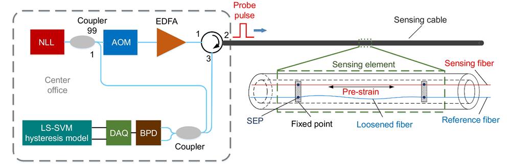
Fig. 1. Schematic diagram of the proposed high-resolution strain sensor network.
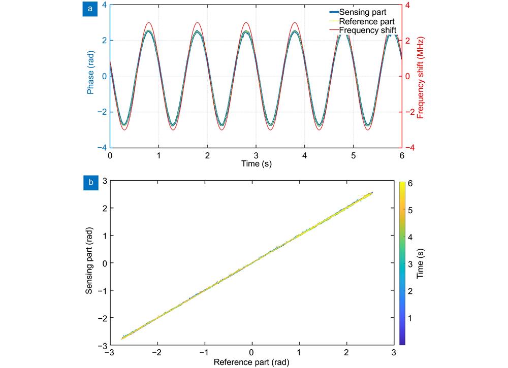
Fig. 2. (a ) Phase change induced by laser frequency shift. (b ) Relationship between the reference channel and sensing channel for laser frequency shift.
Fig. 3. (a ) Phase change induced by temperature fluctuation. (b , c ) Enlarged images for phase change. (d ) Relationship between the reference channel and sensing channel for temperature fluctuation.
Fig. 4. Hysteresis operator. (a ) Relay operator. (b ) Play operator.
Fig. 5. Block diagram of the LS-SVM based hysteresis model.
Fig. 6. (a ) Received beat frequency signal. (b ) Beat frequency signal of sensor element 55 and 54.
Fig. 7. The relationship between phase change and strain.
Fig. 8. (a ) Temperature change waveform and corresponding phase change for model train. (b ) Hysteresis loops for temperature change and the regression result. (c ) Compensation error.
Fig. 9. (a ) Original phase signal for temperature change and strain signal. (b ) Compensation results for two methods. (c ) PSD of the original result and compensation results.
Fig. 10. (a ) Original phase signal in a quiet environment. (b ) Compensation results for two methods. (c ) Noise floor PSD of the original result and compensation results.


Set citation alerts for the article
Please enter your email address

© Copyright 2018-2021 | Chinese Laser Press. All Rights Reserved 沪ICP备15018463号-20