Hua-Ying Liu, Minghao Shang, Xiaoyi Liu, Ying Wei, Minghao Mi, Lijian Zhang, Yan-Xiao Gong, Zhenda Xie, Shining Zhu, "Deterministic N-photon state generation using lithium niobate on insulator device," Adv. Photon. Nexus 2, 016003 (2023)

Search by keywords or author
- Advanced Photonics Nexus
- Vol. 2, Issue 1, 016003 (2023)

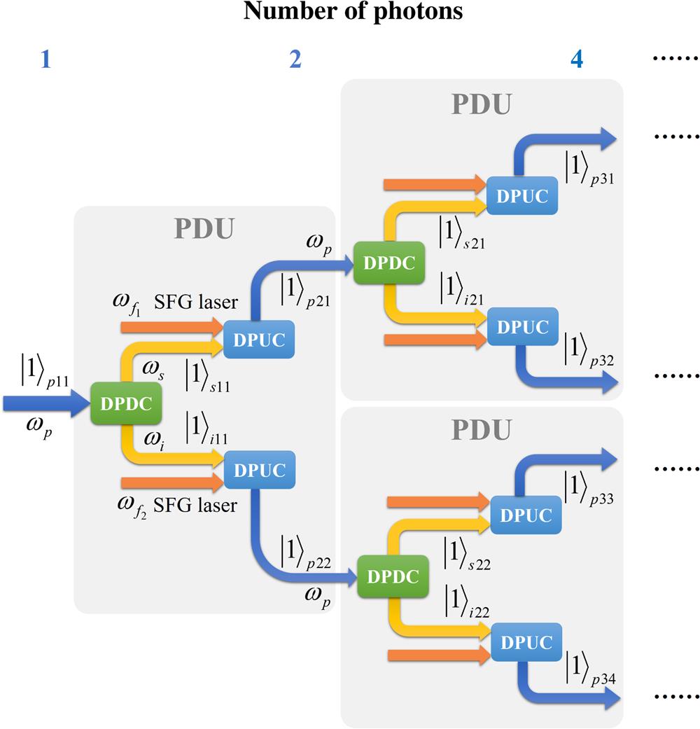
Fig. 1. Scheme for deterministic -photon state generation using the PDU. As marked in a gray box, a PDU is used to convert a pump photon to a biphoton with the same frequency deterministically, through nondegenerate DPDC and DPUC processes. By cascading the PDUs, the photon number can be doubled exponentially, toward deterministic generation of an -photon state, with the Fock state as an example.

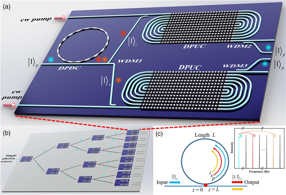
Fig. 2. The example for the PDU and -photon state realization on a LNOI chip. (a) The PDU layout. The DPDC is implemented by a PPLNOI microring resonator and the DPUC is realized by PPLNOI spiral waveguides. In our scheme, the total size for the PDU module is , forming by a radius microring for the DPDC and a 10-mm waveguide for the DPUC, with a minimum bending radius of . (b) On-chip scheme for -photon state generation using cascaded PDUs. (c) A simplified model of the DPDC process in a microring resonator. Here we model the DPDC as a one-dimensional interaction following the propagation of pump, signal, and idler photons, where the coupling point is marked in red for . The coordinate in the resonator varies between 0 and , where is the resonator length. The inset shows longitudinal modes for the pump, signal, and idler photons.

Fig. 3. Calculation results of the PDC and PUC efficiency in the LNOI circuit. (a) The relation between the PDC efficiency and for parametric light, the ripple of the conversion efficiency arises from the Rabi-like oscillation between and . (b) The relation between the required for DPDC and the radius of the microring. The inset is the transverse structure of the simulated LNOI waveguide. (c) The upconversion efficiency with different waveguide lengths and SFG1 laser power . The blue curve indicates DPUC, where multiple DPUC lines indicate Rabi-like oscillation between low-frequency and high-frequency photons. (d) The upconversion efficiency with different waveguide lengths and SFG2 laser power .

Fig. 4. Circuit design for generating different -qubit states. (a) Circuit design for the -photon cluster state. BSs are 50:50 beam splitters for photon separation and interference, and crossers are used for two waveguides to intersect with negligible crosstalk. After 2 stages of PDU, a 4-photon cluster state can be generated in which , , , and . (b) Circuit design for the -photon GHZ state, where after two stages, a 4-photon GHZ state can be generated. The darkened part in this figure is the PDU, of which the detailed structure is shown in Fig. 2(a) .

Set citation alerts for the article
Please enter your email address