• Journal of Semiconductors
  • Vol. 41, Issue 6, 061101 (2020)
Chuen-Keung Sin, Jingzhao Zhang, Kinfai Tse, and Junyi Zhu
Author Affiliations
  • The Chinese University of Hong Kong, Hong Kong, China
  • show less
    DOI: 10.1088/1674-4926/41/6/061101 Cite this Article
    Chuen-Keung Sin, Jingzhao Zhang, Kinfai Tse, Junyi Zhu. A brief review of formation energies calculation of surfaces and edges in semiconductors[J]. Journal of Semiconductors, 2020, 41(6): 061101 Copy Citation Text show less
    (Color online) Workflow of Wulff construction: (I) draw a -plot (black line) in which is used as a normalization constant; (II) draw planes (green line) at every point on the -plot that are perpendicular to the line drawn from the origin to that point; (III) Wulff shape is obtained as the inner convex hull and "ears" appear as indications of missing angles of the Wulff shape.
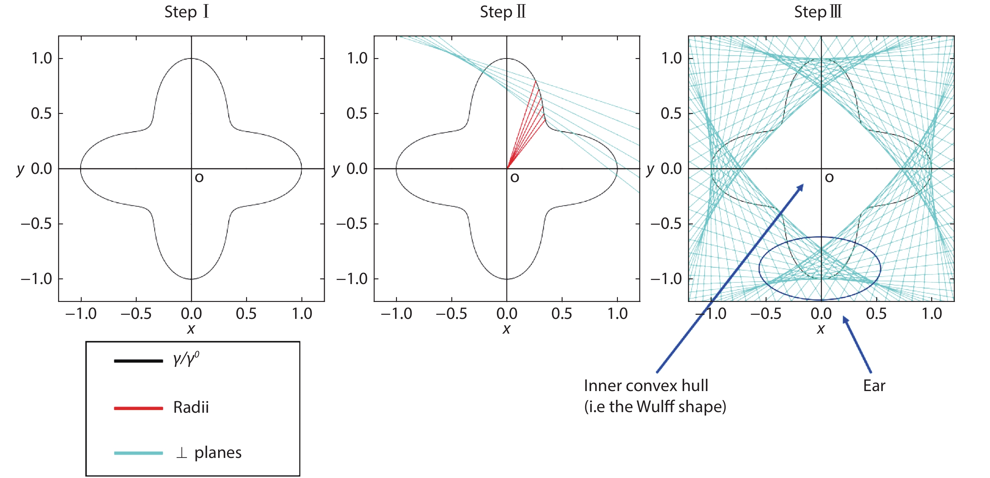
    Fig. 1. (Color online) Workflow of Wulff construction: (I) draw a -plot (black line) in which is used as a normalization constant; (II) draw planes (green line) at every point on the -plot that are perpendicular to the line drawn from the origin to that point; (III) Wulff shape is obtained as the inner convex hull and "ears" appear as indications of missing angles of the Wulff shape.
    (Color online) A slab created by cleaving a zinc-blende structure in (111) plane, grey and yellow atoms represent atom species A and B. Note the resultant upper and lower surface is of different termination.
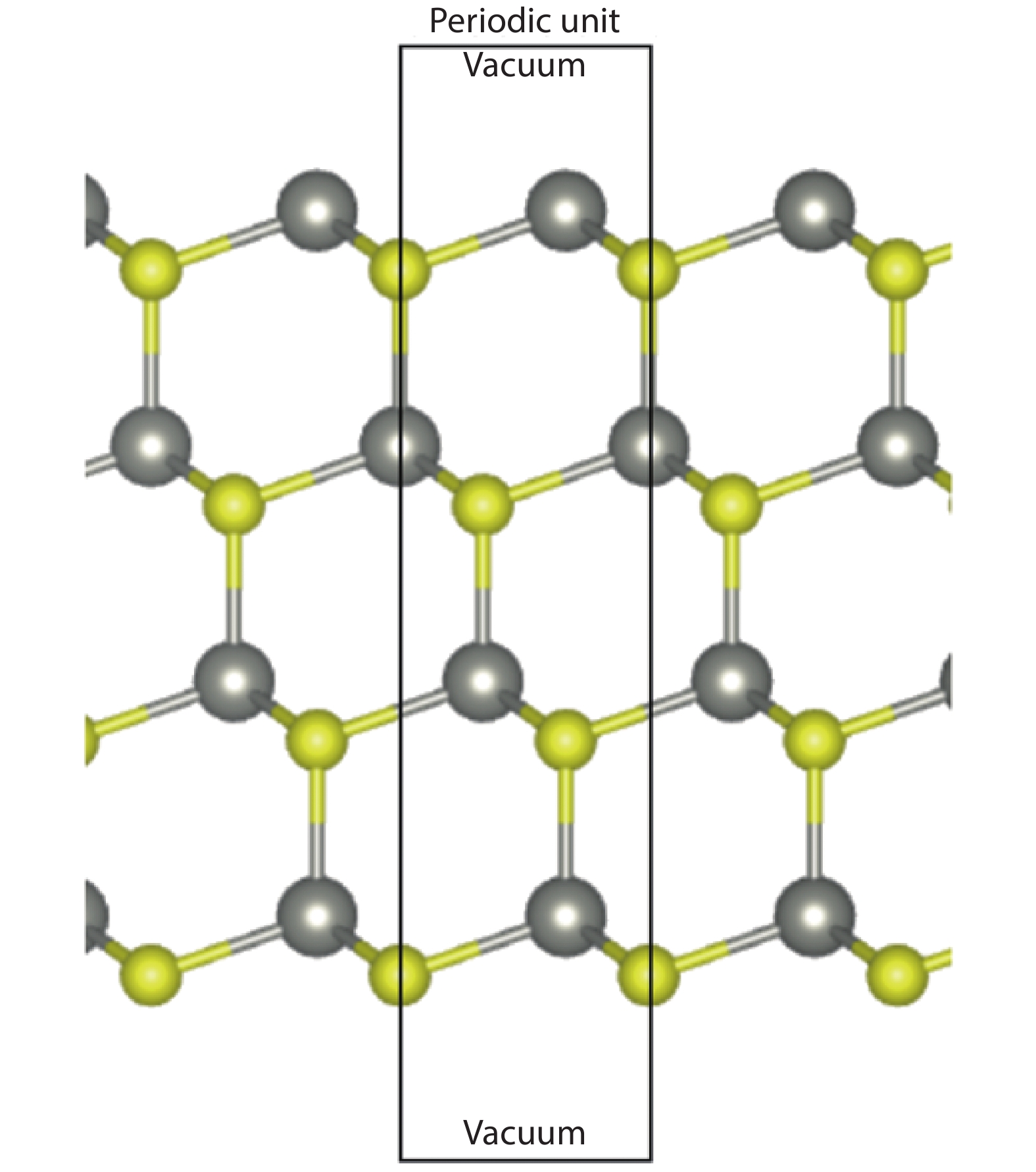
    Fig. 2. (Color online) A slab created by cleaving a zinc-blende structure in (111) plane, grey and yellow atoms represent atom species A and B. Note the resultant upper and lower surface is of different termination.
    (Color online) Wedge structure of size n = 4 composed of two equivalent (111) and one (001) surface used in the calculation scheme of Zhang et al.[44].
    Fig. 3. (Color online) Wedge structure of size n = 4 composed of two equivalent (111) and one (001) surface used in the calculation scheme of Zhang et al.[44].
    An illustration of a slab containing an interface and two passivated surfaces.
    Fig. 4. An illustration of a slab containing an interface and two passivated surfaces.
    (Color online) A ZB(111)/WZ(001) heterojunction supercell consists of 6 WZ and ZB layers used in the calculation scheme of Tang et al.[4]. Note the two interfaces indicated by dashed lines are inequivalent in that ion termination at the interface exchanged.
    Fig. 5. (Color online) A ZB(111)/WZ(001) heterojunction supercell consists of 6 WZ and ZB layers used in the calculation scheme of Tang et al.[4]. Note the two interfaces indicated by dashed lines are inequivalent in that ion termination at the interface exchanged.
    (Color online) Tetrahedral cluster of zinc-blende structure of size n = 4 composed of identically passivated (111) surfaces, passivated edges and corners. The figure is adapted from Ref. [60].
    Fig. 6. (Color online) Tetrahedral cluster of zinc-blende structure of size n = 4 composed of identically passivated (111) surfaces, passivated edges and corners. The figure is adapted from Ref. [60].
    (Color online) GaN crystal with 3 different types of surface cut. The semi-polar one is highlighted pink.
    Fig. 7. (Color online) GaN crystal with 3 different types of surface cut. The semi-polar one is highlighted pink.
    (Color online) Wulff construction of one of the 2D cross-sections of GaN. The yellow shaded area is a quarter of ECS in the cross-section. This strategy is from Ref. [9].
    Fig. 8. (Color online) Wulff construction of one of the 2D cross-sections of GaN. The yellow shaded area is a quarter of ECS in the cross-section. This strategy is from Ref. [9].
    (Color online) Workflow of finding the difference in crystal plane radii. Blue and black notations correspond to unrelaxed and relaxed surface structures respectively. This strategy is from Ref. [9].
    Fig. 9. (Color online) Workflow of finding the difference in crystal plane radii. Blue and black notations correspond to unrelaxed and relaxed surface structures respectively. This strategy is from Ref. [9].
    (Color online) (a) and (b) are slabs with upper semi-polar surfaces of m- and a-family, respectively, and with bottom side cut into step-structure in which the non-polar and polar surfaces are passivated by either H or pseudo-H. These figures are adapted from Ref. [48].
    Fig. 10. (Color online) (a) and (b) are slabs with upper semi-polar surfaces of m- and a-family, respectively, and with bottom side cut into step-structure in which the non-polar and polar surfaces are passivated by either H or pseudo-H. These figures are adapted from Ref. [48].
    (Color online) Slab with a well being cut with width and depth as w and d, respectively, that mimic the steric effects between pseudo hydrogen at the concave corner between the polar and non-polar plane. This figure is adapted from Ref. [48].
    Fig. 11. (Color online) Slab with a well being cut with width and depth as w and d, respectively, that mimic the steric effects between pseudo hydrogen at the concave corner between the polar and non-polar plane. This figure is adapted from Ref. [48].
    (Color online) Cross section view of AlN triangular wedge with surface () and (0001) which are passivated by hydrogen. Orange, silver and red spheres represent Al, N and H atoms respectively. The area bounded by a black line demonstrates that the removal of the area creates a smaller wedge. The strategy is from Ref. [49].
    Fig. 12. (Color online) Cross section view of AlN triangular wedge with surface ( ) and (0001) which are passivated by hydrogen. Orange, silver and red spheres represent Al, N and H atoms respectively. The area bounded by a black line demonstrates that the removal of the area creates a smaller wedge. The strategy is from Ref. [49].
    (Color online) (a)/(c) and (b)/(d) are the (top view/side view) of h-BN and nanoribbon with edges of opposite polarities, respectively.
    Fig. 13. (Color online) (a)/(c) and (b)/(d) are the (top view/side view) of h-BN and nanoribbon with edges of opposite polarities, respectively.
    (Color online) (a) The computational setup for triangular clusters with green dots as boron atoms and silver dots as nitrogen atoms. (b) The result of equilibrium shapes at different chemical potential ranges[107] in which blue, red and black are ZB, ZN and AC edges, respectively.
    Fig. 14. (Color online) (a) The computational setup for triangular clusters with green dots as boron atoms and silver dots as nitrogen atoms. (b) The result of equilibrium shapes at different chemical potential ranges[107] in which blue, red and black are ZB, ZN and AC edges, respectively.
    (Color online) (a) The triangular clusters of different sizes enclosed by two triangles with length and . (b) Structure of four main type of zigzag edges. Other reconstructions of edges were also studied but they are not important in the final equilibrium shape. For details please refer to Ref. [51].
    Fig. 15. (Color online) (a) The triangular clusters of different sizes enclosed by two triangles with length and . (b) Structure of four main type of zigzag edges. Other reconstructions of edges were also studied but they are not important in the final equilibrium shape. For details please refer to Ref. [51].
    (Color online) Equilibrium shape of under different chemical potential of S atoms constructed by Wulff construction. The figure is adapted from Ref. [51].
    Fig. 16. (Color online) Equilibrium shape of under different chemical potential of S atoms constructed by Wulff construction. The figure is adapted from Ref. [51].
    (Color online) B, N and H atoms are denoted by pink, blue and white spheres respectively. (a) Passivated and unpassivated zigzag and armchair edges. (b) Reconstruction of seven- and five- rings on the ZZN and ZZB edges, respectively. (c) Ribbon of bottom zigzag edged passivated with hydrogen and arbitrary configuration on the upper zigzag edge. (d) N-terminated passivated triangular cluster of size m = 5. (d) Bare N-terminated triangular cluster with corner distortion as indicated by red circle. (a) Ribbon with fully passivated zigzag edges. The figure is adapted from Ref. [3].
    Fig. 17. (Color online) B, N and H atoms are denoted by pink, blue and white spheres respectively. (a) Passivated and unpassivated zigzag and armchair edges. (b) Reconstruction of seven- and five- rings on the ZZN and ZZB edges, respectively. (c) Ribbon of bottom zigzag edged passivated with hydrogen and arbitrary configuration on the upper zigzag edge. (d) N-terminated passivated triangular cluster of size m = 5. (d) Bare N-terminated triangular cluster with corner distortion as indicated by red circle. (a) Ribbon with fully passivated zigzag edges. The figure is adapted from Ref. [3].
    (Color online) Total energy of H-passivated triangular clusters with different size (m) and the corresponding non-linear fitting. The figure is adapted from Ref. [3].
    Fig. 18. (Color online) Total energy of H-passivated triangular clusters with different size (m) and the corresponding non-linear fitting. The figure is adapted from Ref. [3].
    (Color online) Equilibrium shapes of h-BN nanocluster under different chemical potentials at 1300 K, consisting of H-passivated edges. Yellow, green and black lines are of ZZBH, ZZNH and ARMH edges respectively. The figure is adapted from Ref. [3].
    Fig. 19. (Color online) Equilibrium shapes of h-BN nanocluster under different chemical potentials at 1300 K, consisting of H-passivated edges. Yellow, green and black lines are of ZZBH, ZZNH and ARMH edges respectively. The figure is adapted from Ref. [3].
    Chuen-Keung Sin, Jingzhao Zhang, Kinfai Tse, Junyi Zhu. A brief review of formation energies calculation of surfaces and edges in semiconductors[J]. Journal of Semiconductors, 2020, 41(6): 061101
    Download Citation