
Xue Wang, Junfeng Jiang, Shuang Wang, Kun Liu, Tiegen Liu, "All-silicon dual-cavity fiber-optic pressure sensor with ultralow pressure-temperature cross-sensitivity and wide working temperature range," Photonics Res. 9, 521 (2021)
- Photonics Research
- Vol. 9, Issue 4, 521 (2021)
Abstract
1. INTRODUCTION
Pressure sensing can provide rich interaction force information related to the object and is of significant importance in artificial intelligence input devices [1], electronic skin [2,3], organ system medical pressure monitoring [4], gas-pressure monitoring [5], and industry applications [6]. Piezo-resistivity-based pressure sensors making use of physic-electronic transduction are the most common sensor type because of their easy signal readout capability. Many micronanostructures, such as ultrathin gold nanowires [7] and urchin-like hollow carbon spheres [8], were proposed to enhance transduction efficiency. However, electronical sensors still suffer electromagnetic interference, a narrow working temperature range, a small pressure measurement range, and large temperature cross-sensitivity, which make them unusable in a harsh environment. For example, pressure sensing at a high-temperature compressor can play an important role in aeroengine investigation and its active control [9–11]. The compressor exit temperatures are on the order of
In recent years, fiber-optic pressure sensors fabricated by employing the microelectromechanical systems (MEMS) technology [12–16] have attracted a great deal of attention because of the feasibility of mass production and high consistency. Anodic bonding technology is the usual way to form a sealed vacuum Fabry–Perot (F–P) microcavity between glass and silicon. The pressure sensitivity can be easily adjusted by designing the thickness of elastic silicon diaphragm and the microcavity diameter. Due to the microcavity diameter of MEMS, fiber-optic pressure sensors are not limited to the diameter of the optical fiber [17]; a
Using real-time temperature measurement to compensate for the pressure-temperature cross-error is an alternative method. For example, a hybrid fiber-optic Fabry–Perot interferometer (FPI) fabricated by double-sided anodic bonding of a through-hole-array-structured glass wafer and two silicon wafers for simultaneous pressure and temperature measurement was proposed [15], or temperature information was obtained by fluorescent material glued near the anodic bonding structure [16]. Nevertheless, the degree of temperature compensation effectiveness will depend largely on the temperature stability of the sensor. The compensation may fail in high-precision measurement when the thermal stress has not been eliminated completely. Therefore, reducing temperature cross response is an essential issue to be solved in order to improve pressure measurement accuracy under a wide dynamic temperature range.
Sign up for Photonics Research TOC. Get the latest issue of Photonics Research delivered right to you!Sign up now
In this paper, an all-silicon dual-cavity fiber-optic pressure sensor is proposed and demonstrated. A silicon substrate and a silicon diaphragm with etched cylindrical cavity are bonded together by silicon/silicon direct bonding to form a sealed vacuum F–P cavity for pressure sensing. The vacuum cavity and the silicon substrate act as two microcavities in series connection. We theoretically analyze the effect of thermal stress and residual gas pressure on pressure measurement, which indicates that the low-temperature cross-sensitivity can fundamentally improve the accuracy of pressure measurement over a wide temperature range. The all-silicon structure fabricated with direct bonding solves the problem of interface thermal mismatch, gas building up in the sealed microcavity, and additional reflective coating. The experiment results show that the pressure sensitivity is of
2. SENSOR CONFIGURATION AND OPERATION PRINCIPLE
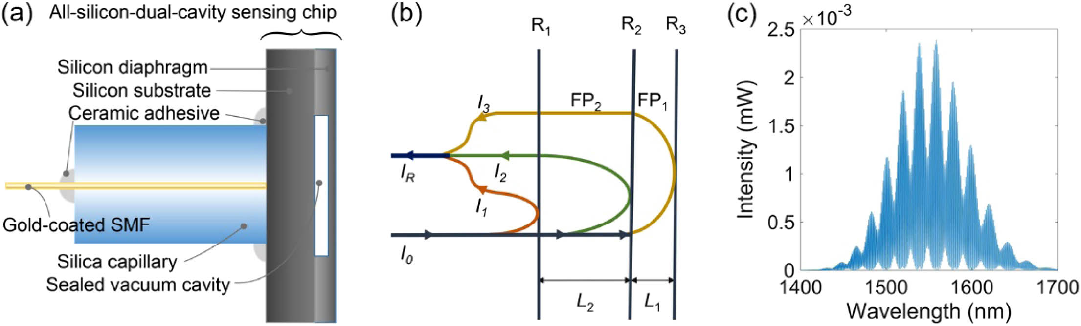
Figure 1.(a) Schematic diagram of the all-silicon-based dual-cavity fiber-optic pressure sensor structure. (All the components are high-temperature resistant materials.) (b) Interference model of the dual-cavity structure with three reflective mirrors; (c) simulation of reflected spectra
A. Analysis of Sensing Characteristics of the Vacuum Cavity
![]()
Figure 2.All-silicon sensing chip’s mechanical deformation when external pressure and residual pressure are applied to it. Schematic diagram of the length and thickness of each part of the sensing chip.
![]()
Figure 3.Simulation results of the nonlinear response characters of the sensor model based on anodic bonding. (a) OPD response of
With our proposed all-silicon structure, there is almost no thermal stress at the bonding interface. Thus, Eqs. (10) and (11) will be simplified to constant values as
B. Temperature Characteristics of the Silicon Cavity
The pressure cross-sensitivity
The temperature sensitivity
According to Eqs. (12) and (17), the variation of OPDs corresponding to
3. SENSOR FABRICATION
The all-silicon sensing chip is fabricated by employing MEMS technology. A silicon-on-insulator (SOI) wafer with a device layer of
![]()
Figure 4.Fabrication processes of the proposed FPI sensing chip. (a) Spin the photoresist on the surface of the device layer of the SOI wafer; (b) photolithograph with the pre-prepared mask; (c) etch the cavity array by dry etching; (d) remove the photoresist; (e) prebond the SOI wafer with the silicon wafer; (f) anneal the prebonded wafer; (g) remove the handle layer and buried oxide layer by dry etching; (h) roughen the surface of the device layer by ultraviolet laser; (i) dice the bonded wafer into independent sensing chips; (j) assemble the sensing chip with silica capillary and gold-coated SMF.
![]()
Figure 5.Pictures of different parts of the fiber-optic pressure sensor structure. (a) Complete sensor after the MEMS process and package; (b) sectional view of a sensing chip and the inset is the detailed section view under a microscope; and (c) top view of the whole wafer before being roughened.
4. RESULTS AND DISCUSSION
A. Sensor Response to the Pressure Variation
![]()
Figure 6.Experimental configuration for investigation of the pressure characteristic of the sensor.
![]()
Figure 7.Example of the demodulation process from the reflection spectra. (a) Recorded interference spectra under 20°C and 100 kPa; (b) OPD results after taking fast Fourier transform of the reflection spectra.
According to the thin plate or small deflection theory [19], the maximum deformation of silicon diaphragm should be less than 20% of its thickness to ensure that the deformation changes linearly with external pressure. Thus, the maximum measurement pressure is about 385 kPa. The experiment was carried out when the temperature of the thermostat was stabled at
![]()
Figure 8.Demodulation results of OPDs’ response to pressure from 20 to 280 kPa at low temperatures. The demodulation results corresponding to (a) vacuum cavity
On the other hand, as Fig. 8(b) shows, the OPD of
B. Sensor Response to the High-Temperature Variation
![]()
Figure 9.Experimental configuration for the investigation of the high-temperature characters of the sensor.
![]()
Figure 10.Demodulation results of OPDs’ response to high temperature from 100°C to 700°C under atmosphere environment. The demodulation results corresponding to (a) vacuum cavity
From Fig. 10(a), it can be observed that OPD of the vacuum cavity
In Fig. 10(b), the OPD response of the silicon cavity
In summary, from the discussion above, the sensor shows the ultralow temperature cross-sensitivity and excellent stability during the high-temperature cycle experiment. Pressure and temperature can be simultaneously obtained by solving the following matrix equation:
Comparison of the Proposed Fiber-Optic Pressure Sensors in Terms of Structure, Pressure Sensitivity, Temperature Cross-Sensitivity, and Pressure-Temperature Cross-Sensitivity
| Type | Structure | Pressure Sensitivity | Temperature | Pressure-Temperature |
|---|---|---|---|---|
| MEMS | The present work | 33.034 nm/kPa | 0.197 nm/°C | 5.96 Pa/°C |
| Silicon-glass-silicon double-sided anodic bonding [ | 12.816 nm/kPa | 3.365 nm/°C | 263 Pa/°C | |
| Silicon-glass anodic bonding [ | ||||
| Silicon-glass thermal compression bonding [ | 47.26 nm/kPa | 3.4 nm/°C | 71.9 Pa/°C | |
| All sapphire direct bonding [ | ||||
| All-silica | SMF-MMF-silica diaphragm [ | 24.8 nm/kPa | 1.48 nm/°C | 60 Pa/°C |
| SMF-HC-PBF-HCF [ | 1.336 nm/kPa | 0.1 nm/°C | 74 Pa/°C | |
| Fiber-tip air bubble FPI [ | 24.44 nm/kPa | 2.6 nm/°C | 106 Pa/°C | |
| SMF with side-open F–P cavity [ | 4.071 pm/kPa (wavelength shift) | 0.83 pm/°C (wavelength shift) | 204 Pa/°C | |
| SMF fabricated by femtosecond laser [ | 0.56 nm/kPa | 15.86 Pa/°C |
5. CONCLUSION
In this paper, we theoretically analyzed the factors that influence the temperature cross-sensitivity of a microcavity pressure sensor. An all-silicon dual-cavity fiber-optic pressure sensor was successfully fabricated. The sensing chip comprises two silicon layers, which are bonded together by direct bonding. A sealed vacuum F–P microcavity was formed between the silicon substrate and the silicon diaphragm for pressure sensing. The silicon substrate acts as the second solid microcavity for temperature sensing. The sensor can eliminate the influence of thermal stress and residual pressure greatly. The experiment results showed that the ultralow pressure-temperature cross-sensitivity of
References
[1] S. Sundaram, P. Kellnhofer, Y. Li, J. Zhu, A. Torralba, W. Matusik. Learning the signatures of the human grasp using a scalable tactile glove. Nature, 569, 698-702(2019).
[2] C. Wang, D. Hwang, Z. Yu, K. Takei, J. Park, T. Chen, B. Ma, A. Javey. User-interactive electronic skin for instantaneous pressure visualization. Nat. Mater., 12, 899-904(2013).
[3] C. Pang, G. Lee, T. Kim, S. M. Kim, H. N. Kim, S. Ahn, K. Suh. A flexible and highly sensitive strain-gauge sensor using reversible interlocking of nanofibers. Nat. Mater., 11, 795-801(2012).
[4] J. Shin, Y. Yan, W. Bai, Y. Xue, P. Gamble, L. Tian, I. Kandela, C. R. Haney, W. Spees, Y. Lee, M. Choi, J. Ko, H. Ryu, J. Chang, M. Pezhouh, S. Kang, S. M. Won, K. J. Yu, J. Zhao, Y. K. Lee, M. R. MacEwan, S. Song, Y. Huang, W. Z. Ray, J. A. Rogers. Bioresorbable pressure sensors protected with thermally grown silicon dioxide for the monitoring of chronic diseases and healing processes. Nat. Biomed. Eng., 3, 37-46(2018).
[5] F. Yang, F. Gyger, L. Thévenaz. Intense Brillouin amplification in gas using hollow-core waveguides. Nat. Photonics, 14, 700-708(2020).
[6] X. Zhou, Q. Yu, W. Peng. Fiber-optic Fabry–Perot pressure sensor for down-hole application. Opt. Lasers Eng., 121, 289-299(2019).
[7] S. Gong, W. Schwalb, Y. Wang, Y. Chen, Y. Tang, J. Si, B. Shirinzadeh, W. Cheng. A wearable and highly sensitive pressure sensor with ultrathin gold nanowires. Nat. Commun., 5, 3132(2014).
[8] L. Shi, Z. Li, M. Chen, Y. Qin, Y. Jiang, L. Wu. Quantum effect-based flexible and transparent pressure sensors with ultrahigh sensitivity and sensing density. Nat. Commun., 11, 3529(2020).
[9] W. J. Pulliam, P. M. Russler, R. S. Fielder. High-temperature high-bandwidth fiber optic MEMS pressure-sensor technology for turbine-engine component testing. Proc. SPIE, 4578, 229-238(2002).
[10] W. Ma, Y. Jiang, H. Gao. Miniature all-fiber extrinsic Fabry–Pérot interferometric sensor for high-pressure sensing under high-temperature conditions. Meas. Sci. Technol., 30, 025104(2019).
[11] H. Zhang, J. Liu, J. Li, P. Jia. Miniature all-silica microbubble-based fiber optic Fabry-Perot pressure sensor with pressure leading-in tube. J. Sens., 2019, 5704614(2019).
[12] C. Pang, H. Bae, A. Gupta, K. Bryden, M. Yu. MEMS Fabry-Perot sensor interrogated by optical system-on-a-chip for simultaneous pressure and temperature sensing. Opt. Express, 21, 21829-21839(2013).
[13] W. Li, T. Liang, P. Jia, C. Lei. Fiber-optic Fabry–Perot pressure sensor based on sapphire direct bonding for high-temperature applications. Appl. Opt., 58, 1662-1666(2019).
[14] X. Wang, S. Wang, J. Jiang, K. Liu, M. Xiao, X. Chen, D. Zhang, T. Liu. An MEMS optical fiber pressure sensor fabricated by Au-Au thermal-compression bonding. Proc. SPIE, 10618, 106180J(2018).
[15] J. Yin, T. Liu, J. Jiang, K. Liu, S. Wang, Z. Qin, S. Zou. Batch-producible fiber-optic Fabry–Perot sensor for simultaneous pressure and temperature sensing. IEEE Photon. Technol. Lett., 26, 2070-2073(2014).
[16] X. Jiang, C. Lin, Y. Huang, K. Luo, J. Zhang, Q. Jiang, C. Zhang. Hybrid fiber optic sensor, based on the Fabry–Perot interference, assisted with fluorescent material for the simultaneous measurement of temperature and pressure. Sensors, 19, 1097(2019).
[17] J. A. Guggenheim, J. Li, T. J. Allen, R. J. Colchester, S. Noimark, O. Ogunlade, I. P. Parkin, I. Papakonstantinou, A. E. Desjardins, E. Z. Zhang. Ultrasensitive plano-concave optical microresonators for ultrasound sensing. Nat. Photonics, 11, 714-719(2017).
[18] Z. Ran, Y. Rao, W. Liu, X. Liao, K. Chiang. Laser-micromachined Fabry-Perot optical fiber tip sensor for high-resolution temperature-independent measurement of refractive index. Opt. Express, 16, 2252-2263(2008).
[19] S. P. Timoshenko, S. Woinowsky-Krieger. Theory of Plates and Shells(1959).
[20] T. Liu, J. Yin, J. Jiang, K. Liu, S. Wang, S. Zou. Differential-pressure-based fiber-optic temperature sensor using Fabry–Perot interferometry. Opt. Lett., 40, 1049-1052(2015).
[21] F. G. D. Corte, M. E. Montefusco, L. Moretti, I. Rendina, G. Cocorullo. Temperature dependence analysis of the thermo-optic effect in silicon by single and double oscillator models. J. Appl. Phys., 88, 7115-7119(2000).
[22] G. Liu, Q. Sheng, D. Dam, J. Hua, W. Hou, M. Han. Self-gauged fiber-optic micro-heater with operation temperature above 1000°C. Opt. Lett., 42, 1412-1415(2017).
[23] X. Wang, S. Wang, J. Jiang, K. Liu, P. Zhang, W. Wu, T. Liu. High-accuracy hybrid fiber-optic Fabry-Pérot sensor based on MEMS for simultaneous gas refractive-index and temperature sensing. Opt. Express, 27, 4204-4215(2019).
[24] X. Wang, S. Wang, J. Jiang, K. Liu, X. Zhang, M. Xiao, H. Xiao, T. Liu. Non-destructive residual pressure self-measurement method for the sensing chip of optical Fabry-Perot pressure sensor. Opt. Express, 25, 31937-31947(2017).
[25] X. Guo, J. Zhou, C. Du, X. Wang. Highly sensitive miniature all-silica fiber tip Fabry–Perot pressure sensor. IEEE Photon. Technol. Lett., 31, 689-692(2019).
[26] Z. Zhang, J. He, B. Du, F. Zhang, Y. Wang. Measurement of high pressure and high temperature using a dual-cavity Fabry–Perot interferometer created in cascade hollow-core fibers. Opt. Lett., 43, 6009-6012(2018).
[27] S. Liu, Y. Wang, C. Liao, Y. Wang, J. He, C. Fu, K. Yang, Z. Bai, F. Zhang. Nano silica diaphragm in-fiber cavity for gas pressure measurement. Sci. Rep., 7, 787(2017).
[28] S. Wu, G. Yan, C. Wang, Z. Lian, X. Chen, S. He. FBG incorporated side-open Fabry–Perot cavity for simultaneous gas pressure and temperature measurements. J. Lightwave Technol., 34, 3761-3767(2016).
[29] Y. Zhang, L. Yuan, X. Lan, A. Kaur, J. Huang. High-temperature fiber-optic Fabry–Perot interferometric pressure sensor fabricated by femtosecond laser. Opt. Lett., 38, 4609-4612(2013).


Set citation alerts for the article
Please enter your email address

© Copyright 2018-2021 | Chinese Laser Press. All Rights Reserved 沪ICP备15018463号-20