
Yuan-Yuan PAN, Li-Na WANG, Jian-Wei LIU, Hui WANG, Shuang CHEN. Design and experiments of 94 GHz Gyrotron for non-lethal biological effects of millimeter wave radiation[J]. Journal of Infrared and Millimeter Waves, 2020, 39(2): 163
- Journal of Infrared and Millimeter Waves
- Vol. 39, Issue 2, 163 (2020)
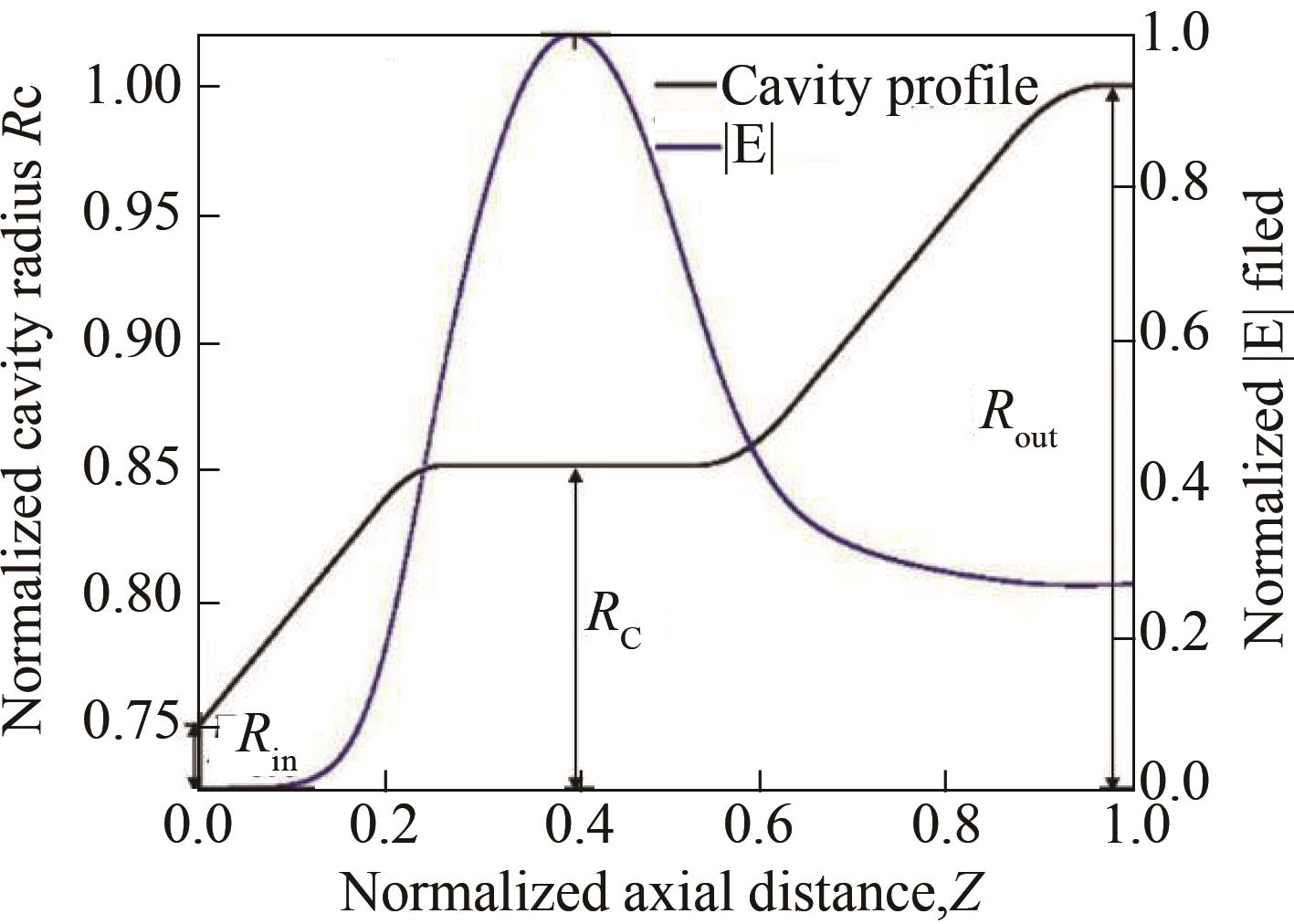
Fig. 1. The cavity structure and distribution of electric field relationship
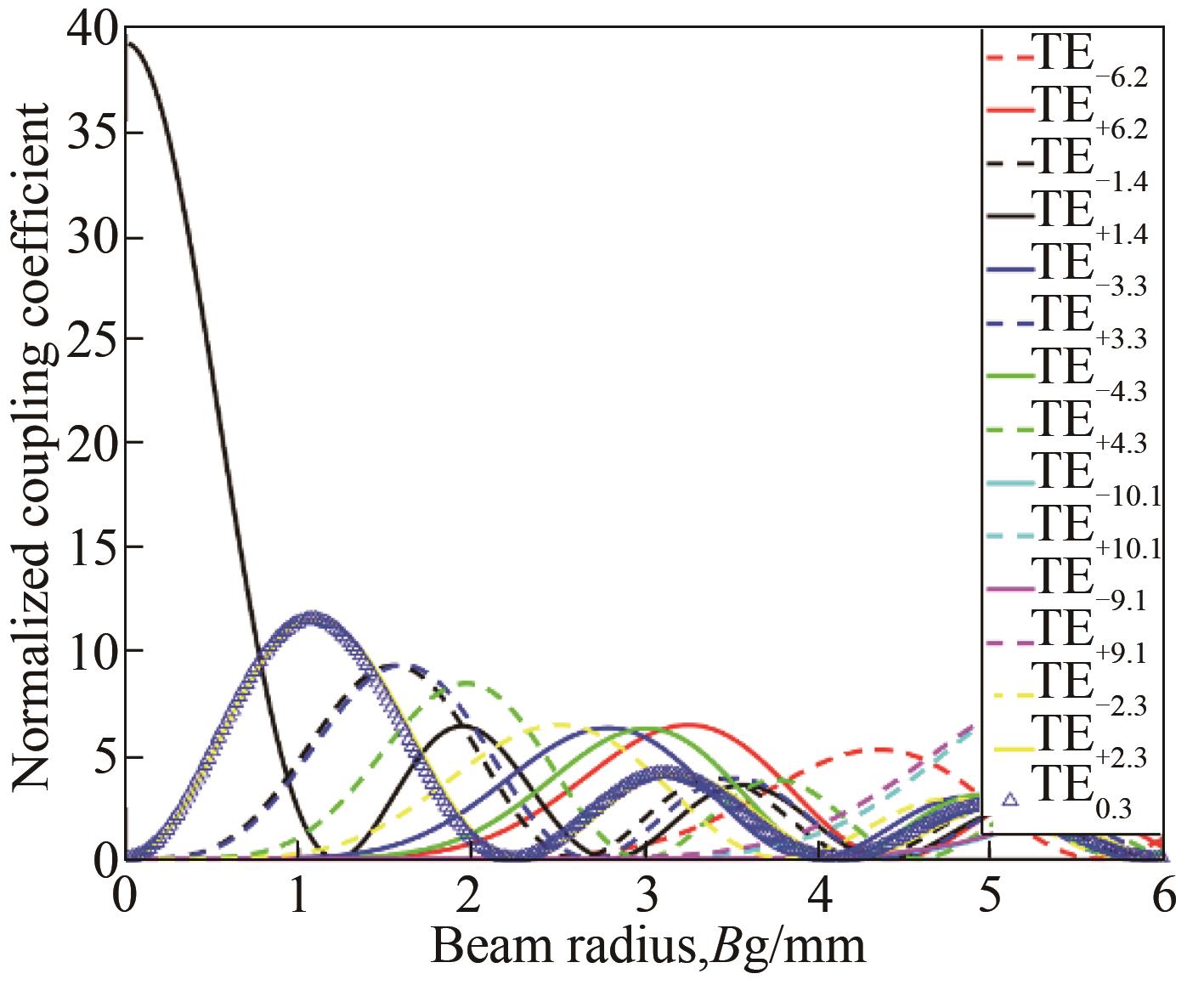
Fig. 2. The normalized beam-wave coupling coefficient of the dominant and competitive modes varies with beam radius
Fig. 3. The starting current of the operating mode and the main competitive mode varies with the external magnetic field, where the beam voltage of 30 kV, beam radius of 3.3 mm and transverse-to-axial velocity ratio of 1.3 were selected
Fig. 4. The startup of multi-mode beam-wave interaction, where the beam voltage of 40 kV, beam current of 4A, transverse-to-axial velocity ratio of 1.3, beam radius of 3.3 mm
Fig. 5. The trajectory and structure of the designed MIG
Fig. 6. Overall diagram of electromagnetic wave transmission process on YOZ plane
Fig. 7. output window field distribution by Electromagnetic simulation
Fig. 8. Photo of the designed gyrotron with quasi-optical mode converter
Fig. 9. The field pattern on a piece of paper at 0.6m from the gyrotron output window
Fig. 10. Rabbit fixed on a wooden board
|
Table 1. Optimized beam parameters and MIG geometry
|
Table 2. The relative power distribution of the 9 modes that form the Gaussian distribution
|
Table 3. Data from the experimental test

Set citation alerts for the article
Please enter your email address
© Copyright 2018-2021 | Chinese Laser Press. All Rights Reserved 沪ICP备15018463号-20