
Yuan-Yuan PAN, Li-Na WANG, Jian-Wei LIU, Hui WANG, Shuang CHEN. Design and experiments of 94 GHz Gyrotron for non-lethal biological effects of millimeter wave radiation[J]. Journal of Infrared and Millimeter Waves, 2020, 39(2): 163
- Journal of Infrared and Millimeter Waves
- Vol. 39, Issue 2, 163 (2020)
Abstract
Introduction
Based on the working mechanism of electron cyclotron devices, high-power gyrotron tubes are the source of millimeter-wave and terahertz-wave radiation [
Due to the needs of the application, the gyrotron needs to work at higher frequencies, higher power and higher efficiency. At the same time, with the increase of output power, the high-frequency structure of the gyrotron increases continuously, and it often works in the high-order mode, which brings difficulties to the transmission and mode conversion of electromagnetic waves. For example, for a gyrotron with an output power of 1 MW and a conversion efficiency of 50%, increasing the conversion efficiency by 1% means that the lost power will be reduced by 0.005 MW [
In recent years, the biological effects of millimeter wave radiation have attracted much attention. Because of its short wavelength and poor penetration, millimeter wave radiation is easily absorbed by tissues with more water content. Therefore, the local effects of millimeter wave radiation are mainly skin and eye damage effects. This study combines the rabbit behavior and skin damage effects in 94 GHz high power millimeter wave radiation, aiming to provide experimental basis for exploring the skin damage effects and mechanisms of high-power millimeter wave radiation.
The rest of this paper is organized as follows. In Sect. 1, this part starts with characteristics of mode selection. Then, one continues with the cold cavity design, followed by the hot cavity analysis. Subsequently, the magnetron injection gun is presented. The part concludes with the quasi-optical mode converter with high power efficiency and loss diffraction. The measured results of the gyrotron are shown in Sect. 2. Finally, one makes a summary in Sect. 4.
1 Theory and simulation
1.1 Mode selection and cold cavity analysis
In order to achieve greater output power, the operating mode should select a high-order mode of 94 GHz. The traditional low-order waveguide mode does not work well, but Higher-order modes cause mode competition. Therefore, it is necessary to study the relationship between working mode and cavity further. In order to suppress the parasitic mode near the working mode, a gradual cavity is used [
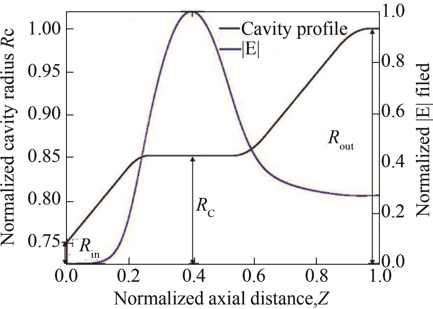
According to the result of numerical calculation, the diffraction quality factor of the main mode TE6.2 is 1 150, and the resonance frequency is 94.19 GHz. The cross section of the optimized cavity with the radius Rc =5.96 mm, input port Rin =5.25 mm and output port Rout =7 mm are shown in
![]()
Figure 1.The cavity structure and distribution of electric field relationship
After the design of the cold cavity is completed, the appropriate beam radius should be carefully selected to achieve the purpose of suppressing the competition mode and obtaining a good beam-wave interaction between the main mode and the electron beam. According to the beam-wave coupling equation of Ref.1,
![]()
Figure 2.The normalized beam-wave coupling coefficient of the dominant and competitive modes varies with beam radius
By analyzing
![]()
Figure 3.The starting current of the operating mode and the main competitive mode varies with the external magnetic field, where the beam voltage of 30 kV, beam radius of 3.3 mm and transverse-to-axial velocity ratio of 1.3 were selected
As shown, the TE+6.2 mode can be started separately in the appropriate magnetic field range. By changing the external magnetic field, the purpose of suppressing the competition mode can be achieved. In summary, we can think of the TE+6,2 mode as the desired gyrotron normal mode of operation.
1.2 Analysis of multi-mode beam-wave interaction
After the design of cold-cavity and the studies of linear analysis, one need to the beam-wave interaction. Multi-mode simulation of a 94 GHz single-cavity gyrotron using the in-house developed non-linear time-dependent code [
![]()
Figure 4.The startup of multi-mode beam-wave interaction, where the beam voltage of 40 kV, beam current of 4A, transverse-to-axial velocity ratio of 1.3, beam radius of 3.3 mm
1.3 Study of Magnetron Injection Gun
According to the requirements of output power and efficiency, the best parameters of electron beam are given by the simulation results of the interaction cavity. The optimum value of the electron beam parameters is also given. Based on the theory of electron guns, the goal of MIG design is to emit electron beams at specific radial positions. Meanwhile, the electron beam has minimum velocity spread and the best velocity ratio. In view of these objectives, the optimized parameters include: cathode and anode geometry, the gap between them, the tilt length of the cathode, the cathode tilt angle, the cathode magnetic field distribution, and the anode voltage. In order to meet the parameters of the gyrotron, we developed a numerical code for designing the MIG and calculated the lateral velocity and longitudinal velocity distribution to be 2.7% and 4.0%. The trajectories and structure are shown in
![]()
Figure 5.The trajectory and structure of the designed MIG
| Parameters | Values |
|---|---|
| Beam voltage | 40 kV |
| beam current | 4 A |
| average radius | 3.3 mm |
Beam pitch ratio Cavity Magnetic field | 1.3 3.540 T |
Table 1. Optimized beam parameters and MIG geometry
1.4 Quasi-optical mode converter
One has developed a high power gyrotron operating at a frequency of 94 GHz TE6,2 mode. Due to the high output power, when the electromagnetic field is output longitudinally, a heat distribution pattern is formed on the output window in the form of TE6,2, which is unevenly distributed and is prone to stress and causes the output window to rupture. At the same time, the TE6,2 mode electromagnetic waves directly output from the circular waveguide are distributed in a conical distribution in free space and cannot be directly utilized. Therefore, this paper uses a Denisov type launcher and four prebunching mirrors to improve the utility of the gyrotron and convert TE6,2 into a fundamental Gaussian mode.
A harmonically deformed launcher is used in the system [
TE4,3 3% | TE7,2 11% | TE10,1 3% |
|---|---|---|
TE3,3 11% | TE6,2 44% | TE9,1 11% |
TE2,3 3% | TE5,2 11% | TE8,1 3% |
Table 2. The relative power distribution of the 9 modes that form the Gaussian distribution
Optimizing the perturbation of the waveguide wall enables a specific Gaussian field distribution to be obtained. Therefore, the design of the specific structural parameters of the launcher is very important. The radius of the launcher is different at each position (ϕ, z). The change in radius can be expressed by the following formula
where φ is the azimuthal angle, is the longitudinal disturbance amplitude, and is the azimuth disturbance amplitude. is half of the longitudinal wavenumber difference between the longitudinal coupling modes, z is the longitudinal position and is half of the longitudinal wavenumber difference between the azimuthal coupling modes. and are the azimuth disturbance periods of the longitudinal disturbance term and the azimuth disturbance term, respectively.
where R0 is the initial radius of the circular waveguide, R0 =7.07 mm, t is the slope of wall radius taper of the launcher, = 0.003.
The wave beam is radiated from the launcher and propagates through a reflection system consisting of a four-sided mirror to the output window. The first mirror is an elliptical mirror, the second mirror is a parabolic mirror, and the other two mirrors are phase correcting mirrors. Both correction mirrors satisfy the Katsenelenbaum-Semenov algorithm. The mirror system adjusts the shape, convergence, and direction of the Gaussian beam to achieve enough energy for non-fatal biological effects.
After the analysis of the basic theory, we create a model in the FEKO (Electromagnetic simulation software). It is shown in
![]()
Figure 6.Overall diagram of electromagnetic wave transmission process on YOZ plane
![]()
Figure 7.output window field distribution by Electromagnetic simulation
According to the above theoretical analysis and numerical simulation, the Gaussian content of the outgoing wave beam to the target function at the output window is about 93%, and the conversion efficiency of the entire mode converter is about 98.54%.
2 Experimental results
2.1 The results of gyrotron
The corresponding W-band gyrotron is designed and manufactured using the above simulation results. The gyrotron has a single-anode magnetron injection gun, single cavity and single stage recessed collector.
In
| Parameters | Values |
|---|---|
| Cathode voltage | 41.2 kV |
| Cathode current | 3.6 A |
Anode voltage Frequency | 8 kV 94.03 GHz |
| Output power | 50.9 kW |
Table 3. Data from the experimental test
The gyrotron with quasi-optical mode converter is shown in
![]()
Figure 8.Photo of the designed gyrotron with quasi-optical mode converter
![]()
Figure 9.The field pattern on a piece of paper at 0.6m from the gyrotron output window
2.2 Results of microwave action on non-fatal biological effects
As we can see in
![]()
Figure 10.Rabbit fixed on a wooden board
3 Summary
This paper designs a 94 GHz gyrotron for non-fatal biological effects. The experiment achieved a 50.9 kW operation with a Gaussian beam output. Based on the steady nonlinear self- consistent field theory, 34.3% of the interaction efficiency can be obtained by using TE6,2 as the working mode. To get good output power, we use a system consisting of a transmitter and four mirrors to focus the beam while adjusting the wave front phase to avoid divergence and side lobes in the output beam. The energy of the launcher is transmitted to the output window through the mirror system, achieving a power transmission efficiency of 98.54% or more.
The experimental results show that a high efficiency gyrotron can be obtained in practical applications if certain conditions are met. For this non-fatal biological effect test, we can draw conclusions that the overall scheme can 6 W/cm2 of 94 GHz high-power millimeter-wave radiation causes rabbit skin recoverable damage. The degree of damage increases with increasing radiation dose, which provides an experimental basis for further research.
References
[1] M V Kartikeyan, E Bore, M K A Thumm. Gyrotrons high power microwave and millimeter wave technology. NY(2004).
[2] M Y Glyavin, N S Ginzburg, A L Goldenberg. THz gyrotrons: status and possible optimizations. Terahertz Sci. Tech, 5, 67-77(2012).
[3] D Weide. Applications and outlook for electronic terahertz technology. Opt.Photonics News, 14, 48-53(2003).
[4] P H Siegel. Terahertz technology in biology and medicine. IEEE Trans. Microw Theory Tech, 52, 2438-2447(2004).
[5] V L Granatstein, G S Nusinovich. Detecting excess ionizing radiation by electromagnetic breakdown of air. . Appl. Phys, 108, 063304-063309(2010).
[6] S Sabchevski, T Idehara. 1. 2(2011).
[7] D L Woolard, E R Brown, M Pepper. Terahertz frequency sensing and imaging: A time of reckoning future applications. Proceedings of the IEEE, 93, 1722-1743(2005).
[8] Q X Zhao, Y Sheng. The nonlinear designs and experiments on a 0.42-THz second harmonic gyrotron with complex cavity. IEEE Transactions on Electron Devices, 64, 564-570(2017).
[9] G Guo, X Niu, Y Liu. e2593. Devices and Fields(2019).
[10] G Zhao, Q Z Xue, Y Wang. Design of quasi-optical mode converter for 170-GHz TE32,9-Mode high-power gyrotron. IEEE Transactions on Plasma Science, 47, 2582-2589(2019).
[11] G G Denisov, M I Petelin, D V Vinogradov. 6. PCT Gazette, 16, 47-49(1990).
[12] V Dmitry, G G Denisov, M I Petelin. Art. no, 19291(1992).
[13] J Jin, M Thumm, B Piosczyk. Novel numerical method for the analysis and synthesis of the fields in highly oversized waveguide mode converters. IEEE Trans. Microw. Theory Tech, 57, 1661-1668(2009).
[14] J Jin, M Thumm, G Gantenbein. A numerical synthesis method for hybrid-type high-power gyrotron launchers. IEEE Trans. Microw. Theory Techn, 65, 699-706(2017).
[15] X Niu, C Lei, Y Liu. A study on 94 GHz low-voltage, low-current gyrotron. IEEE Transactions on Electron Devices, 60, 3907-3912(2013).
[16] Q Liu, Y Liu, X Niu. Theoretical investigation on a multifrequency multimode gyrotron at Ka-band. IEEE Transactions on Plasma Science, 45, 2955-2961(2017).
[17] P Ruifeng, G S Nusinovich, O V Sinitsyn. Numerical study of efficiency for a 670GHz gyrotron. Phys. Plasmas, 18, 023107(2011).
[18] A Bogdashov, G G Denisov. Asymptotic theory of high-efficiency converters of higher-order waveguide modes into eigenwaves of open mirror lines. Radiophys. Quant. Electon, 47, 283-296(2004).
[19] J B Jin, B Piosczyk, M Thumm. Quasi-optical mode converter/mirror system for a high-power coaxial-cavity gyrotron. IEEE Trans. Plasma Sci, 34, 1508-1515(2006).

Set citation alerts for the article
Please enter your email address
© Copyright 2018-2021 | Chinese Laser Press. All Rights Reserved 沪ICP备15018463号-20