Abstract
Herein, an attention-grabbing and up-to-date review related to major multiplexing techniques is presented which includes wavelength division multiplexing (WDM), polarization division multiplexing (PDM), space division multiplexing (SDM), mode division multiplexing (MDM) and orbital angular momentum multiplexing (OAMM). Multiplexing is a mechanism by which multiple signals are combined into a shared channel used to showcase the maximum capacity of the optical links. However, it is critical to develop hybrid multiplexing methods to allow enhanced channel numbers. In this review, we have also included hybrid multiplexing techniques such as WDM-PDM, WDM-MDM and PDM-MDM. It is probable to attain N×M channels by utilizing N wavelengths and M guided-modes by simply utilizing hybrid WDM-MDM (de)multiplexers. To the best of our knowledge, this review paper is one of its kind which has highlighted the most prominent and recent signs of progress in multiplexing techniques in one place. Herein, an attention-grabbing and up-to-date review related to major multiplexing techniques is presented which includes wavelength division multiplexing (WDM), polarization division multiplexing (PDM), space division multiplexing (SDM), mode division multiplexing (MDM) and orbital angular momentum multiplexing (OAMM). Multiplexing is a mechanism by which multiple signals are combined into a shared channel used to showcase the maximum capacity of the optical links. However, it is critical to develop hybrid multiplexing methods to allow enhanced channel numbers. In this review, we have also included hybrid multiplexing techniques such as WDM-PDM, WDM-MDM and PDM-MDM. It is probable to attain N×M channels by utilizing N wavelengths and M guided-modes by simply utilizing hybrid WDM-MDM (de)multiplexers. To the best of our knowledge, this review paper is one of its kind which has highlighted the most prominent and recent signs of progress in multiplexing techniques in one place.Introduction
The relentless pressure for higher data rates ensured the rapid growth of optical components, allowing the terabits (Tbits) of today’s data rates to be enjoyed1, 2. All began with exceptionally lossy fiber optics (hereafter represented as FOs) coupled with a broadband source that could only relay a few Mb/s over a few meters. For half a century, the situation improved dramatically, accomplishing data rates of even Tbit/sec conceivable over a single FO. With the development of external cavity lasers (ECL), it is possible to obtain linewidths below 1 MHz3, 4, Mach-Zehnder modulators (MZM)5, 6 that can simply function at 40 Gb/s and beyond7, low attenuation dispersion operated FOs, dispersion compensation FOs, optical amplification networks and high-speed detectors that render numerous compensation hardware redundant. Multiplexing is the mechanism by which multiple signals are merged into a shared channel used to tap the maximum volume of the optical links8. Multiplexing has traditionally been used to share the medium’s inadequate bandwidth (hereafter abbreviated as BW) between multiple transmitters, but it is all about maximum usage of the immense available BW for optical networks.
This is where wavelength division multiplexing (WDM) comes in where numerous channels are multiplexed into a single FO. WDM was implemented as an advance in delivering high volume data broadcast by letting various wavelength channels be concurrently transmitted in a particular FO9. Polarization-division-multiplexing (PDM) is one more distinguished strategy to increase data broadcast ability with two polarized channels10. In recent times, mode-division multiplexing (MDM) has appeared as a prospective method to upturn the data broadcast size by using numerous spatial guided-modes in multimode waveguides (WGs), which can increase multi-fold optical link volume by employing merely a single wavelength source11. MDM tends to be highly appealing for imminent network-on-chip computing because there is no need for an array of precise wavelength lasers like WDM networks. Hybrid multiplexing methods, for instance, MDM-WDM12 and MDM-PDM13, have also been introduced. MDM communication has been established with several modes in Si photonic integrated circuits (PICs), in which each mode signified a distinct information channel14-16. Numerous constructions, for example, multimode interferometers (MMIs)17, asymmetric directional couplers (ADCs)18 and adiabatic mode-evolution couplers19 among others, have been introduced as PICs MDMs.
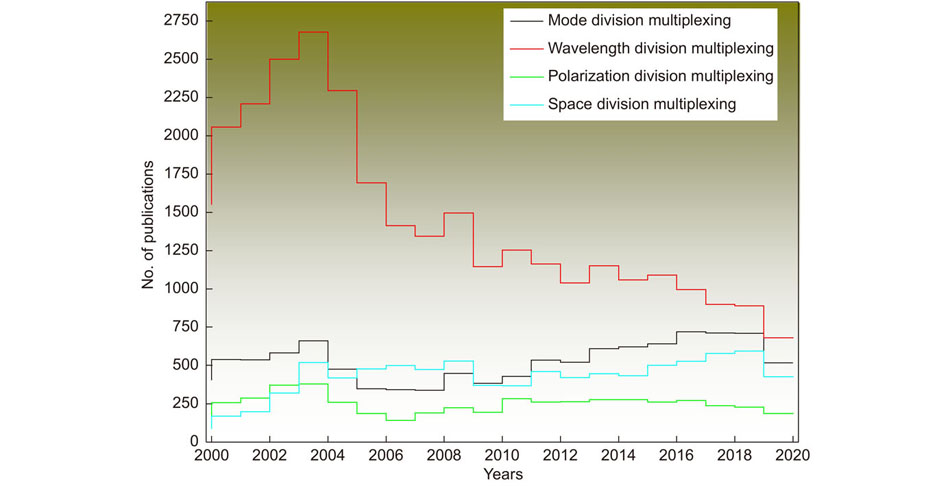
Optical multiplexing is an imperative topic and intense research is carried out every year throughout the world. Several research articles based on different multiplexing techniques, for example, WDM, MDM, SDM and PDM among others are published on regular basis. Figure 1 depicts the number of publications on multiplexing topics published in 2000-2020 indexed in the Scopus database. In the year 2020, we can see a significant decrease in the number of publications which can be attributable to the inadequate research activities during COVID-19. In the Image Processing Systems Institute of the Russian Academy of Science, we have fabricated several diffractive optical elements for the realization of MDM in free-space20, 21 and in FO22, 23. Based on our experience in this vast field, we have tried our best to review recent advancements in the world of multiplexing. The topics covered in this review are WDM, PDM, SDM, MDM, OAMM and three hybrid techniques such as WDM-PDM, WDM-MDM and PDM-MDM. Only the most prominent works are highlighted and cited in this paper.

Figure 1.The number of research papers associated with different multiplexing techniques indexed in the Scopus database.
Over the past 4 decades, several industrial advances have endorsed the FO volume to upsurge by about 10 times every four years as seen in Fig. 2. Until now, broadcast infrastructure has been able to continue with the persistent rapid evolution of Internet protocol traffic. The cost of sending additional data was still practicable, primarily because more data was transmitted over the same FO by customizing the FO end apparatus. However, a growing number of FOs will surpass their performance in actual networks over the next decade or so24. Besides, this constraint of FO volume is not explicit to a particular modulation scheme; rather it is necessary to derive from a basic expansion of the Shannon volume limit for a nonlinear FO channel under reasonably general beliefs25. The drawback is that at spectral efficiency of ~10 bit/s/Hz, a typical single-mode fiber (SMF) will hold no more than 100 Tbit/s of data equal to the C and L amplification wavelength regime of an erbium-doped fiber amplifier.
Figure 2.The advancement of transmission volume in FOs established by the state-of-the-art laboratory.
The paper is organized in the following manner: At first, the recent advances in the major multiplexing techniques such as wavelength division multiplexing (WDM), polarization division multiplexing (PDM), space division multiplexing (SDM), mode division multiplexing (MDM) and orbital angular momentum multiplexing (OAMM) are discussed and it is revealed that how multiplexing is vital to boost the capacity of the optical link. It is important to progress hybrid multiplexing techniques to permit higher channel numbers. Afterwards, hybrid multiplexing techniques such as WDM-PDM, WDM-MDM and PDM-MDM are discussed and recent developments in this topic have been presented. The authors of this paper are working on this topic for more than 3 decades. In the end, a section related to the authors’ contribution to the multiplexing field is presented followed by the concluding remarks.
Wavelength division multiplexing (WDM)
Network BW is like the wardrobe in your home, you will never get plenty of it. And the data flow is making the demand for communication volume expand faster than the teenager’s wardrobe with a no-limit credit card. Short email messages are being switched to BW-hogging animated graphics. Data, video, and voice signal broadcast networks that had sufficient space just a few years ago. Now, the telecom sector wants out of the box approaches to fulfill the never-ending need for BW. WDM technology enables optical channels to be concurrently transmitted via a single FO at different wavelengths, which is a valuable source of making full usage of the low-loss characteristics of FOs over a large wavelength range. The term WDM is generally used for an optical carrier (usually defined as wavelength), while frequency-division multiplexing (FDM) is usually used for a radio carrier (which is most frequently termed as a frequency). Meanwhile, wavelength and frequency are connected by a directly inverse correlation, the two expressions represent a similar notion. The use of the orthogonal-frequency-division-multiplexing (OFDM) format for passive optical networks has piqued researchers’ interest recently. OFDM signals have high spectral efficiency, a high tolerance for fiber chromatic dispersion, and a great degree of flexibility when it comes to multiple service provisioning and dynamic BW allocation26-29.
The theory was first proposed by Delange in 197030, but it was in the mid-1977 that basic research on WDM technology had only begun. The research focused on practical implementations for communication networks31, 32. Since then, exploration has accelerated, along with histrionic development in FOs, light sources and photodetectors (PDs). In particular, optical multiplexer/demultiplexers (MUX/DEMUX), which are the main elements in the WDM broadcast networks, are at present among the most common R&D methods. A WDM network employs a MUX to connect the signals at the transmitter, and a DEMUX to break them apart at the receiver. It is probable to provide a network that does this concurrently and can act as an optical add-drop MUX with the proper type of FO. Etalons, thin-film-coated optical glass-based single-frequency Fabry–Pérot interferometers have historically been used as optical filtering devices. Several types of MUX/DEMUX have been suggested and produced for data purposes.
Figure 3.Schematic representation of one-directional WDM broadcast.
Even though WDM technology is not currently fully grown, it has been increasingly employed in functional networks in some countries. Predictably, this technology will dominate shortly optical communication infrastructure. This is largely owing to the outstanding use of WDM, which is focused on the employment of the broad low-loss spectrum region in FOs. Currently, WDM technology is one of the widespread study and expansion topics and several review articles have already been published33, 34. The basic configuration of the one-way WDM broadcast is shown in Fig. 3. The benefits of WDM networks are increase in broadcast size per fiber, reduction in network cost, concurrent broadcast of multiple modulation-scheme signals, and service channel expandability after FO implementation. Because of these reasons WDM technology is supposed to be broadly installed in diverse fields of optical communication networks.
Generally, WDM networks are used by telecom enterprises because it facilitates the volume expansion of the network deprived of adding more FOs to the network. It is possible to provide numerous generations of technology expansion in their optical network by employing WDM technology and optical amplifiers without renovating the mainstay network. The volume expansion of the given connection can be achieved by merely improving the MUX and DEMUX designs at the transmitter side and receiver side, respectively. In ref.35, a white-lighting (WL) and WDM-visible light communication (VLC) network with a free-space distance of more than 20 meters and a lighting distance of 3 meters is validated by an RGB triple-source polarization-multiplexing scheme, broadcast gratings, and a dual convex lens. Integrating four-level pulse amplitude modulation (PAM-4) with a triple source polarization-multiplexing network, the peak broadcast rate is substantially increased to 300 Gb/s. WL is created by multiplexing the RGB lights with two gratings and disjointed by DEMUX via the other two gratings. By assuming a dual-convex diffuser, the WL is spread over 3 meters of free space to deliver general WL illumination (>100 lux). These verified WL and WDM-VLC networks achieve a high broadcast rate with an indoor lighting target. It would open a novel classification for lighting and optical broadcast. The basis of the suggested WL and WDM-VLC network employing broadcast gratings and a tailored diffuser over a 20-meter FSO link with a 3-meter lighting distance is shown inFig. 4. The images of the experimental setup are also shown in Fig. 4(a), and the detailed experimental results can be found in ref.35.
Figure 4.(a) Graphical illustration of the white-lighting and WDM-VLC network utilizing broadcast gratings and a tailored diffuser over a 20 m FSO link with a 3 m lighting distance. (b) Optical micrographs of the WDM receiver chip. (c) 40 Gbps and 50 Gpbs eye diagrams of channels 5, 10, 15, 20 and 25 at 0 and –1 V. The modulator eye graphs are also displayed for evaluation. Figure reproduced from: (a) ref.35, Optical Society of America; (b) ref.36, Optica Publishing Group, under the Optica Open Access Publishing Agreement.
A novel design of an integrated WDM receiver chip is manufactured on the SOI platform which is equipped with a 25-channel Si nanowire-AWG36. Every channel is incorporated with a Ge-on-Si WG PD. The PDs display a current density of 16.9 mA/cm2 at −1 V and extraordinary sensitivity of 0.82 A/W at 1.55 μm. Wide BWs of 23 GHz and 29 GHz are attained at 0 and −1 Volt, respectively. Every channel can function at 50 Gb/s with low optical input power even below zero bias resulting in a collective data rate of 1.25 Tb/s. The optical micrographs of the receiver chip are revealed in Fig. 4(b). Eye diagrams of channels 5, 10, 15, 20, and 25 at 40 Gb/s and 50 Gb/s were obtained from PD currents between 90 and 110 μA, as displayed in Fig. 4(c). The experimental details can be found in ref.36.
Polarization division multiplexing (PDM)
Multiplexing is an encouraging solution in reply to the ongoing demand for increased broadcast volume. As the most common and advanced form of multiplexing, WDM has been used successfully for many years. With the growing requirement for BW development, dense WDM networks with a range of laser sources are being utilized, resulting in dense and costly deployment. Besides, it is demonstrated that a typical single-mode FO cannot hold more than 100 Tbit/s data due to its physical limitation37. It is also important to introduce new strategies to additionally improve the broadcast BW. The lucrative approach is to multiplex the various aspects of the single-wavelength light carrier such as polarization, referred to as PDM.
A desirable proposal for network operators is to improve the broadcast capability or spectral effectiveness of a current FO network deprived of needing to modify any aspect of the communication hardware or software, so it will dramatically reduce the downtime of the network and decrease the cost of apparatus and connection for network upgrade. One optical method employed to enhance the performance of optical broadcast networks is PDM38. The advantage of PDM is that the broadcast volume is multiplied since separate signals can be distributed over orthogonal positions of polarization of the same light39. The two polarization channels are separated at the receiver end and are independently recognized. Ideally, at each end of the FO link, the operator only needs to install a transceiver and a related polarization MUX/DEMUX, while the residual network is unaffected which includes FOs, repeaters, amplifiers, wavelength MUX/DEMUX, optical add/drop MUX, switching optics and even the network managing software, or with a slight alteration. The spectral performance of the network can be enriched by minimizing the channel wavelength spacing or aggregating the bit rate of the transceiver. In recent times, several schemes are proposed such as monitoring of pilot tones40, 41, multi-level electronic detection42 and cross-correlation recognition of the two demultiplexed channels43. However, this method entails a momentous re-design of the network, and are thus not appropriate for upgrading current networks, although it might be practicable for new networks to be introduced.
Subcarrier multiplexing (SCM) is another method used to improve the BW of optical networks. The SCM technique joins numerous electrical signals having diverse frequencies to be communicated over the same optical light. Passive optical networks (PONs) based on SCM allow multiple consumers to share the optical channel and the related optical apparatuses minimizing the total network cost44. In recent years, the commercial disposal of cost-effective electro-optic modulators with wide frequency ranges and strong linearity has encouraged the use of SCM methods with OFDM-based signals45. The integration of PDM and SCM strategies opens the potential for optical network volume to be maximized.
PDM is a simple method, requiring two channels with orthogonal polarizations to be combined only by a polarization beam combiner (PBC) as shown in Fig. 5. However, it is not easy to distinguish the two channels at the receiving end with tolerable crosstalk (CT), since the polarization positions of the two channels are no longer linear, and randomly change with time. To isolate those with a polarization beam splitter (PBS), it is conceivable to observe the CT of the two channels in real-time and then make use of the scrutinized data to vigorously regulate the positions of polarization of the two polarization channels. To date, no good method of optical CT tracking has been identified; thus, one must depend on the identified electronic signal in the receiver to display CT. Research has been devoted to designing the MUX, as an elementary functional component, with silicon on insulator (SOI) platform46, 47. Likewise, much attention has also been paid to designing the other important modules for example data exchange48, mode filter49, power splitter50, and switch51, among others.
Figure 5.Schematic representation of the PDM network.
Interest in visible light communication (VLC) has gradually grown, fueled by the dramatic growth of LED technology52, 53. Widespread usage, cost-efficient high brightness, improved BW compared to other traditional RF-based devices make it the most capable contender for concurrent lighting and communication mainly in particular areas such as hospitals, aircraft, and high-security prerequisite environments, among others. Though, the comparatively poor intrinsic modulation BW of commercially offered LED is the major technological difficulty in the VLC framework. Recently, a VLC network based on PDM is proposed54. The polarization feature of visible light carries with it another degree of freedom that can multiply the volume of the broadcast. To obtain PDM, two orthogonal groups of polarizers and incoherent RGB LEDs are introduced. Due to the minimal laboratory parameters, the red LED chip of the RGB LED is used. Moreover, the spectrally effective 16QAM Nyquist single carrier frequency domain equalization (SC-FDE) is established. However, it was validated on an optical bench, and hence not suitable for CMOS integration. Division-of-focal-plane (DoFP) polarimeters combined with CMOS technology allow dense, polarization imaging networks55. The DoFP polarimeters are made up of aluminium nanowire materials and attached to custom CMOS chips. This device includes a complete image processing pipeline that runs at frame rates of 40 f/s and thus allows real-time polarization properties to be derived from the imaged environment. Successful incorporation of high-speed photodiodes into CMOS ICs for a functioning CMOS-compatible optical digital clock delivery is established and electrical recovery network in a 0.35 µm CMOS process. This paper shows the feasibility of low-cost optical-electrical signal conversions at GHz speeds56.
In ref.57, a Verilog model of the PDM VLC network is presented. The model is regulated by utilizing the information from manufactured filters and is joint with diode and receiver circuit models. Light is characterized by its three major properties, i.e., wavelength, polarization, and intensity. In this network, the light intensity is used to transport the encrypted data, and polarization to discrete multiple channels. Each input light signal at a diverse polarization angle is modulated to symbolize one digital data channel and joined into one in free space at the source. This incident light is going to form the input to the network. Each data channel has a distinctive polarization angle. In the case of the 2-channel network, the polarization angle of the data channels is 0° and 90°. In the case of the 3-channel network, the data channel polarization angles are 0°, 60° and 120°. Whereas in an event of a 4-channel network, 0°, 45°, 90° and 135° are used as the data channel polarization angles. This combined input light signal is collected by a DoFP polarimeter array which may have 2, 3 or 4 filters depending on the channel design. Each filter from the array will have a polarization angle that matches the polarization angle of one channel of the input light. This work signifies a good starting point to attain improved outcomes for a 4-channel VLC network, plus the usage of channel coding to increase the output. The schematic of the 4-channel VLC network is shown in Fig. 6.
Figure 6.4-channel VLC network. Figure reproduced from ref.57, SPIE.
Space division multiplexing (SDM)
Currently, most optical broadcast networks utilize single-mode fibers (SMFs) to transfer data over long distances. More degrees of freedom are accustomed to improving the data rate of SMFs, such as different wavelengths, both polarizations and quadrature amplitude modulation58. Technologies for instance coherent receivers and more sophisticated signal processing that can reimburse many of the effects that arise during the broadcast to further improve the data capacity of optical broadcast networks. However, with the latest technologies, the data rates or spectral competence that can be attained in an SMF tends to be constrained by noise and non-linearity with a volume of 100 Tbit/s per fiber or a spectral efficiency of about 10 bit/s/Hz37. With a growing request for greater data rates, the last degree of freedom for multiplexing, that is space, has been intensively studied in the last decade as a potential resolution to meet the BW demand.
The schematic representation of the N ×N SDM communication structure is demonstrated in Fig. 7. The signals are primarily produced by N number of transmitters. MDM of the N signals is attained via the spatial-mode multiplexer. Eventually, the signals supported by spatial modes are transferred to the few-mode fiber (FMF). All the modes on the same wavelengths are to be handled as a unit of an SDM super-channel during the broadcast i.e., they are amplified, dropped, and added simultaneously deprived of individual mode processing. After broadcast over FMF, the received signals are then mode DEMUXED by a spatial-mode demultiplexer. Then N coherent receivers detect the demultiplexed signals. The signals are then transformed from an optical-to-electrical domain, electrically sampled with high-speed ADCs, and then analyzed utilizing a DSP module. The MIMO algorithm is employed to compensate for the mode coupling and/or CT in the channel that can be applied at S-MUX/DEMUX or inside the FMF. The channel volume is supposed to be improved by N times as compared to single-mode configuration if the MUX/DEDUX has a unit transfer function with an N-rank equivalent to the number of modes maintained in an SDM FO.
Figure 7.The design of an NxN SDM communication network using coherent MIMO digital signal processing. Where MUX/DEMUX represents multiplexer/demultiplexer and Co-Rx signifies Coherent receiver.
Various parallel spatial channels are employed in SDM to upsurge the data throughput of a broadcast network. Parallel SMF networks can be employed to increase the data rate by the number of utilized FOs to realize SDM as presented in Fig. 8(a). However, with the number of parallel networks, the price and energy ingesting of such parallel networks also surge linearly and there may be attractive methods to realize SDM, where some elements like FOs, amplifiers, transmitters, and receivers can be commonly used between the various spatial channels, reducing the cost/bit. Several distinct methods of implementing SDM with FOs are shown in Fig. 8. Multicore FOs (MCFs) with uncoupled cores are one rather straightforward way59. Each core acts basically as an SMF in such FOs60. The CT between cores is low enough not to damage the performance of each channel when the cores are sufficiently separated, see Fig. 8(b). Many low CT FOs and up to 37 cores have been manufactured and broadcast has been demonstrated over long distances61, 62. Besides, amplifiers have been introduced that can simultaneously amplify all cores63. Mode division multiplexing (MDM) is another method for performing SDM where different orthogonal modes of FO are employed as separate spatial channels to transfer data. FMFs are typically used for the MDM method as shown in Fig. 8(c). FMFs are known as multi-mode fibers (MMFs) that can hold few modes, often in the range of 2–10 modes64, 65. Coupling between the different FO modes should be considered in MDM. When communicating over longer distances, mode coupling is inevitable. There will be a robust coupling between modes of the same mode group, even for short distances. By employing multiple-input-multiple-output (MIMO) signal processing, mode coupling can be restricted.
Figure 8.Different dissimilarities of FOs for SDM. (a) FO bundle, possibly with compact cladding diameter. (b) Multicore FO with uncoupled cores. (c) Few-mode FO. (d) Coupled-core multicore FO. (e) Multi-mode-multicore FO, in which each core supports more than one mode.
Another prospect for SDM is multicore FOs with cores that are adequately close to couple, see Fig. 8(d)66. The light travels between the cores in super-modes and acts analogous to FMF. Integration between multicore and FMFs has also been shown in Fig. 8(e). Here, several cores are supported by each core of the multicore FO and the FO can thus reach an enormous number of spatial channels. Several such FOs and their broadcasts have been demonstrated in ref.67, 68. Besides, SDM can help to address the growing energy consumption of broadcast networks which is in line with the need for higher data speeds69. It is more energy efficient to employ multiple spatial channels rather than optimizing the signal-to-noise ratio by increasing the input power into FOs can maximize the data rate in the FO.
Mode division multiplexing (MDM)
Silicon (Si) photonics has been technologically advanced in the last decade as a result many attractive applications are realized on an SOI platform utilizing the complementary metal-oxide-semiconductor (CMOS) fabrication technology70, 71. Si has a large transparent window covering the near-IR to mid-IR wavelength range, which is critical for achieving low-loss on-chip optical WGs72, 73. Moreover, it is conceivable to have compact photonic devices owing to the high index contrast between the Si core and the SiO2 substrate74, 75. The small footprint helps in decreasing power usage for active Si photonic devices. At present, various Si photonic devices are established with extraordinary performances76-79. Most of the time, PICs are typically equipped with merely fundamental mode because higher-order modes are typically very irritating because of the intolerable CT and propagation loss produced due to multimode interference (MMI)80. Thus, the optical WGs are typically aimed to be single-mode, such that higher-order modes are cut off. The circumstance is currently evolving with the progress of Si photonics having an exceptional feature of its high refractive index difference. Using a variety of different technologies, several on-chip MDM compatible mode MUXs have been presented81-85. In a spot-based approach, most on-chip networks operate and use grating couplers to vertically emit light spots with diverse phases. The intended mode within an FMF can be stimulated by generating the right field pattern above the chip. Different devices have been testified based on the SOI platform86, 87.
Because of their small footprint, low power consumption, and high production output, PICs have demonstrated significant benefits in optical transceivers. For MDM optical interface, multimode chip-to-fiber couplers provide an essential link between PICs and FMF. Chip-based mode MUX/DEMUX and on-chip MDM connectivity have gotten a lot of attention. Several integrated mode converters and multiplexers have been proposed, but only a handful are capable of multimode coupling83. The most difficult part is the multimode interface, which serves as a link between the on-chip multimode WG and the FMF. Chip-to-fiber vertical/edge connection typically uses a grating coupler or a spot size coupler. To meet the huge mode field difference between integrated WG and silica fiber in the case of multimode, specific designs must be used. A pair of 2D grating couplers with significant coupling loss and a push-pull solution was presented for exciting 6 linear polarization modes87. Later, other multimode grating couplers were constructed with a simpler and more compact construction. While the grating coupler’s intrinsic limitation, notably its restricted bandwidth, prevents the application from being compatible with wideband WDM.
Figure 9 displays the dispersion curves of the standard SOI strip WG with a silicon core height of 220 nm88. It is well noted that SOI strip WG has extraordinary birefringence and robust mode dispersion. Consequently, mode-selective modulation with low excess losses and low inter-mode CT can be realized for all the guided modes in a multimode SOI WG even though these guided modes are coincided in space, as displayed in the inset of Fig. 9. This brings the possibility of the use of higher-order modes by incorporating multimode optical WGs in the design of Si photonic devices. Light has a limited range of physical characteristics such as wavelength, polarization, amplitude/phase that can be employed to encrypt data. However, all these encoding methods are approaching their limits and soon the connection speeds will fall far short of demand. There is only one remaining degree of freedom that is still essentially unexplored i.e., “Space”. In this way, space is the final destination of FO communication. In MDM, different spatial profiles (i.e., different shapes) known as modes are allocated light beams for different channels. A straightforward scenario will be sending one channel on a laser beam shaped like a circle, one like a square and one like a triangle. The shapes used are more complex in operation and have unique mathematical and physical features. This technique is arguably the most groundbreaking revolution in how data has been transmitted down FOs since at least the 1980s. MDM method offers a novel tactic for realizing more channels and augmenting the link volume with a single wavelength carrier89. The operation principle of the MDM is shown in Fig. 10.
Figure 9.Effective refractive indices of the guided modes versus width of the core width. Inset shows the mode shapes of the fundamental and higher-order modes. Figure reproduced with permission from ref.88, under a Creative Commons Attribution 4.0 International License.
Figure 10.The operation principle of MDM. The scheme is adapted from ref.90.
In ref.91, a novel scheme of an on-chip two-MDM circuit is proposed by employing tapered directional coupler (DC)-based mode MUX and DEMUX on the SOI platform. The design offers high merits such as low insertion loss of 0.3 dB, low mode CT of < −16 dB, wide BW which is approximately 100 nm. The mode multiplexing testing is performed on the manufactured circuit with non-return-to-zero (NRZ) on-off keying (OOK) signals at 40 Gbit/s. Figure 11(a) displays the manufactured device consisting of a MUX (detail in Fig. 11(b)) at the input side, a multimode data bus WG (750 nm wide), and a DEMUX at the output side. The width of the narrow WG is 355 nm, the wide WG is tapered from 748 nm to 848 nm, and the coupling gap is 100 nm, as presented in Fig. 11(c) and 11(d).
Figure 11.(a) Manufactured TE0 and TE1 mode MUX circuit. (b) SEM images of a manufactured TE0 and TE1 mode (de)MUX and details of its. (c) Input side. (d) Output side91. (e) Graphical representation of a multimode SDM circuit with two polarizations. (f) Schematic of the circuit and structures of (g) μ-RRs-1, (h) μ-RR-2. Figure reproduced from: (a–d) ref.91, Optica Publishing Group, under the Optica Open Access Publishing Agreement; (e) ref.92, Optical Society of America; (f–h) ref.93, Optica Publishing Group, under the Optica Open Access Publishing Agreement.
In ref.92, a compact Si mode (de)MUX with cascaded asymmetrical DCs is verified. A 4-channel mode MUX/DEMUX is considered and comprehended for TM-polarized light. The manufactured device has an excess loss of <1 dB as well as low CT ≤ 23 dB over a wide range of wavelengths. It is possible to add more channels by employing two arrangements of orthogonal-polarization modes (e.g., 2 N=8) multiplexed when preferred. Power splitters split the light from the laser diode into 2N channels. As the power of each channel is 1∕2N, an optical amplifier should be added to reimburse for the loss if necessary. The polarization of half of the channels is alternated via a polarization rotator array. As a result, two orthogonally polarized lights are achieved. The 2N channels are then linked to the 2N optical modulators. These 2N channels are eventually merged with a MUX. At the receiver end, multichannel signals can be demultiplexed with a DEMUX which is then collected by a PD array. As it is typically uncommon for PDs to be susceptible to polarization, polarization rotators are added before the PD array to use the same PDs on the chip, which facilitates streamlining the configuration of the chip. Since merely one laser is required and there is no requirement to critically monitor the wavelength, the administration of the hybrid multiplexing network is easy and the cost is supposed to be minimal. The graphical representation of the demonstrated design is displayed in Fig. 11(e).
A unique on-chip information conversion circuit for the MDM signals is proposed by employing two μ-ring resonators (μ-RRs) established mode converters93. Single and four wavelengths non-return-to-zero on-off-keying signals at 10 Gb/s passed on diverse modes are managed. The bit error ratio results indicate practical power losses. The graphical representation of the proposed circuit is shown in Fig. 11(f). MDM signals encompassing TE0 and TE1 modes transfer into the first μ-RR (μ-RR-1), which achieves the TE1–TE0 mode transformation. The configuration of μ-RR-1 is displayed in Fig. 11(g). The drop port and ring bend WGs of μ-RR-1 are designed to be single-mode, whereas through port WG’s width is precisely tailored to gratify the phase-matching condition in the coupling region between fundamental mode of ring bend WG and TE1 mode of through port WG. TE1 mode signal will be transformed into TE0 mode at the drop port whereas the TE0 mode signal retains unaffected by propagating through μ-RR-1 at the through the port. Instead, the μ-RR-2 works as a TE0-TE1 mode transformer. The assembly of μ-RR-2 is symmetric with μ-RR-1, as displayed in Fig. 11(h).
Orbital angular momentum multiplexing (OAMM)
Due to its potential to provide high-speed wireless transmission, wireless communication employing OAM has recently attracted a lot of attention as an emerging possibility beyond 5G technology. OAM is a physical feature of EM waves in which the propagation path is defined by a helical phase front. Wireless OAMM may effectively boost the transmission rate in a point-to-point link such as wireless backhaul and/or fronthaul since the feature can be exploited to establish numerous separate channels94, 95. Yan et al. established the viability of OAM multiplexing by reaching 32 Gbps transmission utilizing the 28 GHz frequency in 201494 and the 60 GHz band in 201696. Because OAMM is a novel technique, it is critical to test its viability from different viewpoints. In the same way, as multiple-input multiple-output (MIMO) technologies employ multiple antenna elements, this technique does as well. Multiple beams conveying various OAM modes are superimposed using the elements.
Antenna components are linked to phase shifters that rotate n × 360o to form the beam carrying the OAM mode n (L=n). Figure 12(a) depicts an example of OAM mode 0, 1, and 2 beam generation employing uniform circular arrays (UCAs) with eight antenna components. It’s worth noting that for multiple OAM mode generation, it is possible to utilize either a single UCA or multiple UCAs. In the first example, a single UCA transmits superposed beams. Concentric multiple UCAs are employed in the later situation. Separation of OAM-carrying beams can be accomplished in a manner like that used for the generation, with antenna components coupled to phase shifters rotating in different directions. Rotations of n × 360o are orthogonal to one another if the number of antenna elements is more than 2n. As a result, the signals of each OAM mode may be isolated from those of mixed OAM modes without aliasing. Figure 12(b) depicts an example of each antenna element’s phase concerning the previous example. As with beam production, such beam separation can be accomplished using single or multiple UCAs. In the former situation, a divider is installed between the antenna components and phase shifters.
Figure 12.(a) Formation of OAM modes with a UCA. (b) Separation of OAM modes with a UCA.
Many diverse tests have proven the viability of OAMM94, 96, 97. Yan et al. showed 32 Gbps OAMM across a 60 GHz mm-wave band with four concurrent OAM modes (mode=–3, –1, 1 and 3) with 16 QAM modulation. The transmission distance was 2.5 meters, and a 4 to 1 combiner was employed to multiplex 4 SPPs96. Mahmouli et al. used a holographic plate and spiral phase plate to transmit 4 Gbps uncompressed video over a 60 GHz mm-wave frequency97. Over 10 meters, however, no Gbps level transmission trials have been documented. When a UCA is employed for OAM beam production, the capacity upper limit of OAM multiplexing is not superior to that of MIMO technology, according to ref.98. Mohammadi et al. investigated the performance of the system as a whole99. In ref.100, the link budget was examined while the mode dependency of the propagation loss was clarified. Significant research has been done and is currently being done, such as studies on calibration techniques101, examination of the impacts of multipath102, and so on103, in addition to the work described above.
A marriage of WDM, MDM and PDM techniques
Different multiplexing techniques such as WDM, PDM, SDM and MDM are presented in previous sections have been established recently. However, it is attractive to cultivate hybrid multiplexing methods to allow enhanced channel numbers. Numerous Si-based on-chip hybrid MUX/DEMUX are demonstrated by integrating more than one multiplexing technique, as shown in Fig. 13. In this section, we will look at the recent development of on-chip hybrid MUX/DEMUX by utilizing hybrid WDM-PDM, WDM-MDM and PDM-MDM techniques.
Figure 13.Hybrid MUX/DEMUX techniques combing multiple individual methods.
Hybrid WDM-PDM technique
Two attractive techniques such as WDM and the PDM are combined to realize on-chip hybrid WDM-PDM MUX/DEMUX by integrating WDM and polarization manipulating components on the same chip. Array waveguide gratings (AWGs) are widely used in multi-channel WDM networks. Recently, a hybrid WDM-PDM MUX/DEMUX based on the SOI platform is established by incorporating an (N + 1) × (N + 1) bi-directional AWG with a polarization-diversity circuit (PDC). An 18-channel hybrid WDM-PDM MUX/DEMUX comprising of a 10×10 bi-directional AWG MUX/DEMUX and a PDC was established104. The graphical representation of the hybrid MUX/DEMUX is shown in Fig. 14(a). The magnified image of the polarization diversity circuit connecting with the two input WGs of the bi-directional AWG is presented in Fig. 14(b). The PDC consists of a PBS and a polarization rotator (PR). By employing a polarization-selective evanescent coupling in a bent DC, the PBS is apprehended, while the PR is realized in a corner-cut SOI WG by the intervention of two hybridized modes105. Both the PBS and PR operate effectively in a wide wavelength range to be well-suited with the WDM network. The CT and the surplus loss of the AWG could be minimized for realistic applications. One might find that the efficiency of the AWG sturdily relies on the spacing of the channel. The dimensions of the AWG circuit increase as the channel spacing reduces, and more phase errors appear, which introduces larger CT. The channel spacing of 3.2, 2, and 0.8 nm leads to the channel CTs of −17 – −23 dB, −15 – −20 dB, and −9 – −15 dB, respectively106. To realize efficient SOI-WG AWGs with a slender channel-spacing is still very challenging.
Micro-ring resonators (μ-RRs) have also been extensively used for the realization of low-loss and low-CT WDM filters. The μ-RRs based on SOI WGs are quite compact due to the formation of μ-bends78, 72, 107. Consequently, μ-RRs based on the SOI platform typically have a wide free spectral range (FSR) ~20−30 nm, which is adequate for DWDM networks to span several wavelength channels. Additionally, by optimizing the coupling coefficients, box-like filtering feedback is created by adding an array of μ-rings108. A new hybrid PDM-WDM MUX is proposed by incorporating an arrangement of optical filters established on μ-RR and a polarization-splitter-rotator (PSR)47. A configuration comprised of an adiabatic taper, an ADC and an MMI mode filter is used for the PSR demonstrating an outstanding efficiency in a wide wavelength range in comparison with a previously reported device109. To streamline the circuit arrangement and the wavelength synchronization of the μ-RRs, the cross- and through-ports for all the optical filters based on μ-RR of the PSR are linked via the bus WG. More prominently, these μ-RRs are wavelength selective for TE polarized light and offer extremely high ER>35 dB which significantly decreases the polarization CT owing to the PSR.
SDM which involves the use of distinct modes in a FMF, is a recognized prospective technique for tackling the high capacity and high bandwidth density demands in future data centers, owning to the exponential development of data traffic in recent years. A mode multiplexer for FMF that is dependable, efficient, and low-cost is thus urgently desired. Integrated diffraction grating produced on the SOI substrate, in addition to fiber-based photonic lanterns and laser inscribed 3D optical WGs, is a possible contender. Low cost, great reliability, mass-production, and co-integration with other integrated photonic devices such as high-bandwidth transceivers are all apparent advantages of monolithic integration110, 111.
Figure 14.(a) Graphical pattern of the hybrid MUX/DEMUX containing a bi-directional AWG and a polarization diversity circuit. (b) The magnified image of the PDC joining the two input WGs of the bi-directional AWG. Figure reproduced with permission from ref.104, Optica Publishing Group, under the Optica Open Access Publishing Agreement.
Hybrid WDM-MDM technique
One more operational method is to create a hybrid MUX/DEMUX technology that allows WDM and MDM simultaneously to additionally increase the volume of an optical link when N number of wavelengths are accessible. It is conceivable to acquire a high-volume data communication with overall M × N channels when M modes and N wavelengths are available by utilizing multimode optical WGs capable of supporting multiple guided modes112, 67, 14. Recently, Photonic crystals (PhCs) have been suggested for the realization of PICs due to their outstanding efficiency and small footprint114, 115. The photonic bandgap (PBG) produced by the periodically modulated refractive index has been employed in various ways to manipulate light75. Compared to traditional counterparts, several devices have been introduced using PhCs with promising efficiency and footprint116-118. Hybrid WDM/MDM networks have been studied in ref.119-123.
Figure 15.(a) Schematic representation of a silicon hybrid de (multiplexer) for MDM and WDM. (b) SEM image of the manufactured SiN hybrid MDM-WDM device. SEM pictures of the coupling regions between the input WGs and the bus WGs with a designed bus WG width of, (c) 1 μm, (d) 2.25 μm, (e) 3.5 μm. (f) Schematic representation of a hybrid WDM-MDM MUX/DEMUX. Figure reproduced from: (a) ref.124, (b–e)125, Optica Publishing Group, under the Optica Open Access Publishing Agreement; (f) ref.126, Optical Society of America.
A WDM/MDM scheme based on the SOI platform has been presented in ref.124 and the graphical image of the device is displayed in Fig. 15(a). It utilizes strip WGs to realize MMI and DCs for multiplexing. While its performance is acceptable, it has a large footprint. A similar issue has been noted in the devices based on cascaded RRs and DCs125. The SEM image of the manufactured hybrid WDM-MDM device is displayed in Fig. 15(b–e). Recently, a novel design of a hybrid WDM-MDM MUX/DEMUX is suggested which is based on a 2D PhC structure126. The device is capable of simultaneously multiplexing two modes and two wavelengths. WDM and MDM functions are realized by utilizing two identical MMI couplers and asymmetric DCs, respectively. Tapers are employed at WG intersections to evade back reflections. The device has a small footprint which is appropriate for on-chip incorporation. Numerical calculations disclose that the IL and CT are smaller than 1.0927 dB and –11.9024 dB, respectively, for all four channels. The device configuration is shown in Fig. 15(f).
Hybrid PDM-MDM technique
It is still a difficult task to realize innovative devices that allow extra channels for a single wavelength to attain ultra-high-volume optical interconnects. The channel volume can be improved significantly by adding dual polarization or several guided modes. It is undoubtedly conceivable to mix several guided modes and dual polarizations in such a manner that many channels can be acquired for a single wavelength carrier18. Hybrid PDM-MDM MUX/DEMUX is considered as the main component operating with both dual-polarization and multiple modes128-131. On-chip PDM and MDM devices based on the Si platform have recently been documented which can provide ultra-compact, CMOS-compatible, and low-cost modules132. To realize both the polarization and mode MUX/DEMUXs, two methods were proposed, “mode evolution” and “mode coupling”133, 15. A variety of ACs134, MMI couplers135, and Y-branches136 based architectures have been realized for the polarization or a mode MUX/DEMUX in the view of mode evolution approach. While it is possible to obtain wide BWs and high ERs for these devices, due to the mode evolution method, the footprints are relatively large. Various asymmetric directional couplers (ADCs)137, grating-assisted ADCs138, and compactly packed WG arrays (DPWAs)139 have been shown to achieve ultra-compact polarization and mode MUX/DEMUXs for the mode coupling approach. The advantages of multi-core and multi-mode techniques are combined in DPWA structure and rather than employing a single broad multimode WG, the DPWA employs a series of thin SOI wire WGs of varying widths. The effective width of the DPWA bus WG is equivalent to that of a standard multimode WG since these WGs are tightly packed with nanometers size gaps. It is possible to develop an efficient and parallel DEMUX technique with a large working wavelength range. However, among these described MUX/DEMUXs, two polarizations with only one fundamental mode were controlled in a polarization MUX/DEMUX or two modes of only single-polarization were maintained in a mode MUX/DEMUX. For the realization of the on-chip hybrid MUX network, a compact, scalable, and broadband MUX/DEMUX supporting more effective modes on dual-polarization is critical.
In ref.13, a compact Si 10-mode hybrid MUX/DEMUX is demonstrated established on 3-cascaded asymmetric directional couplers (ADCs) based segments, 3-adiabatic tapers, and a PBS. The phase-matching can be attained by changing the widths of the bus WGs and access WGs for the TM modes and TE modes, respectively. The numerical calculations display that a total coupling length for TM1–TM3 and TE1–TE5 modes can be attained to be 55.4 μm. Besides, the aggregate loss of the hybrid MUX/DEMUX can be minimized due to the fewer tapers in comparison with the standard cascaded ADCs. Likewise, PBS is optimized with a small footprint of 7.0 μm and high extinction ratios of 32.9 dB and 15.4 dB for the TM0 and TE0 modes, respectively. The schematic representation of the hybrid MUX/DEMUX is shown in Fig. 16. Moreover, we have listed some most prominent research publications on the multiplexing techniques discussed in this paper as shown in Table 1.
Figure 16.Graphical illustration of 10-mode hybrid MUX/DEMUX device for both TE and TM polarizations. Figure reproduced with permission from ref.13, under a Creative Commons Attribution 4.0 InternationalLicense.
| Ref | Year | IL (dB) | CT (dB) | BW (nm)/∆λch (nm) | MT |
| ref.140 | 2020 | <4 | –9.5 | 70 | MDM |
| ref.141 | 2020 | 0.08, 0.19, 0.03 | 20 | 75 | MDM |
| ref.142 | 2020 | <0.5 | –20 | 80 | MDM |
| ref.143 | 2020 | <1.1 | –18 | 120 | MDM |
| ref.144 | 2013 | <1.5 | <–9 | 100 | MDM |
| ref.145 | 2013 | ~0.3 | <–36 | 100 | MDM |
| ref.91 | 2013 | 0.3 | –16 | 100 | MDM |
| ref.146 | 2021 | 1.6 | 10 | 90 | Hybrid PDM-MDM |
| ref.147 | 2021 | – | –49.93 to –45.8 | 164–310 | WDM |
| ref.148 | 2018 | 0.32 | –30 | 90 | MDM |
| ref.149 | 2020 | – | –23 | 260 | MDM |
| ref.150 | 2019 | – | –25 | 140 | CWDM |
| ref.151 | 2014 | 0.6 | –22 | 35 | Hybrid MDM-WDM |
| ref.104 | 2015 | 7 | –13 | 3.2 | Hybrid WDM-PDM |
| ref.152 | 2016 | 1 | <-22 | 3 | Hybrid WDM-MDM |
| ref.47 | 2018 | 0.5–5.0 | –16.5 | 3.2 | Hybrid WDM-MDM |
Table 1. Few major optical multiplexing papers reported in recent times. IL: Insertion loss, CT: Crosstalk, BW: Bandwidth, MT: Multiplexing technique.
Author’s commentary on multiplexing
In this section, we would like to share some of our contributions related to the multiplexing techniques. In our previous work, we have theoretically and experimentally demonstrated the rotation of multimode light beams153-155, mode division multiplexing23, 156, 20, fabrication of diffractive optical elements for optical expansion of laser fields by the orthogonal basis21, 157-162, diffractive optical elements for spatial multiplexing163-169 and laser ablation and matter structuring170-173. Diffractive optics tools such as diffractive optical elements (DOEs) or spatial light modulators (SLMs) can be used both to efficient multiplexing structured laser beams for free-space optical (FSO) information broadcast or input into single- or multi-core fibers, and subsequent DEMUX of the signal at the output of the broadcast network174. The most advantageous feature of the FSO is the practically unlimited BW at optical frequencies. However, the effects of the natural random media significantly limit the possibilities of the optical broadcast of information in free space. To overcome this problem, researchers suggest using: partially coherent radiation175-182. DOEs are an effective tool not only for generating various types of laser beams but also for their superposition with desired properties which can be used for MDM resistance to FSO turbulence influence183, 153-155. Figure 17 illustrates phase DOEs for efficient generation multimode Laguerre-Gauss beams with 5 desired modes of indices (n, m)=(1, 1)+(3, 1)+(4, –3)+(5, –5)+(5, 1) (the upper row, 16-level phase) and with 6 desired modes of indices (n,m)=(2, 0)+(3, –2)+(3, 2)+(4, –4)+(4, 0)+(4, 4) (the bottom row, binary phase).
Figure 17.Multimode Laguerre-Gauss beams. (a) The DOE phase. (b) The squared modulus of the coefficients in the superposition. (c) The intensity distributions in the focal plane for 5-modes beam (the upper row) and the 6-modes beam (the bottom row). Figure reproduced from ref.154, American Institute of Physics.
Also, utilizing diffractive optics any pattern of modes with preferred weights can be effectively excited in FOs184-188. Figure 18 shows simulation results of excitation and propagation of selected LP modes in a weakly guiding step-index FO.
Figure 18.Propagation of LP modes superposition in a weakly guiding stepped-index FO (the intensity distribution is taken at different distances z) for (p, q)=(1, 2)+(–2, 1) (top row), (p, q)=(3, 2)+(5, 1) (middle row), (p, q)=(4, 1)+(5, 1) (bottom row). Figure reproduced from ref.189, Pleiades Publishing.
DOEs that produce a variety of mode beams in different diffraction orders157-161 are used as spatial filters to investigate the transverse mode characteristic of light and achieve DEMUX at the output of the optical transmitting information network189-192. Figure 19 shows the correlation network with a multi-channel DOE for instantaneous recognition of individual vortex positions of different Laguerre-Gaussian beams arbitrary to offset from the optical axis.
Figure 19.Instantaneous recognition of particular vortex positions of Laguerre–Gaussian beams. (a) The correlation network with a multi-channel DOE. (b) Results of detection (correlation peaks circled in red) in the focal plane. Figure reproduced from ref.192, under a Creative Commons Attribution.
Note that in this case, not only MDM is possible, but also the detection of a variety of polarization positions (MDM+PDM)193-198. Figure 20 shows binary multi-channel DOE for examining the polarization and phase positions of vortex cylindrically polarized beams.
Figure 20.Binary 14-channel DOE for investigating the polarization and phase positions of vortex cylindrically polarized beams. (a) DOE phase. (b) Correspondence of the diffraction orders in the focal plane to the orders of optical vortices198.
There are known works where MDM, PDM and WDM are combined199. Multi-order optical elements matched with the laser modes157, 159, 14, 160, 21 and DOEs for 1D, 2D and 3D spatial multiplexing of different light elements/units/primitives (light spots, rings, lines, etc.)165, 167, 163, 164, 169, 170 can be used to generate beams arrays for SDM200, 201 and perform the simultaneous coupling of light into a set of FOs, including MIMO202, 203, 156, 67, 204, 205. Figure 21 illustrates multi-channel binary phase DOE matched with LP modes of a step-index FO which can be used to detect 64 modes simultaneously. The results and discussion should be presented in a logical sequence in the text, tables, and figures; repetitive presentation of the same data in different forms should be avoided. This section should consider the experimental results concerning any hypotheses advanced in the Introduction.
Figure 21.(a) The binary phase of the encoded 64-order DOE, matched with LP modes of a step-index FO. (b) The experimentally recorded intensity distribution in the focal plane of the lens when the DOE is illuminated by a plane wave. (c) The arrangement of LP-modes indices
,
(the conjugate modes with indices
are located symmetrically in the lower part). Figure reproduced with permission from ref.156, under a Creative Commons Attribution 4.0 International License.
Concluding remarks
In conclusion, we have presented a detailed review of the recent advances in multiplexing techniques that can be utilized in fiber optics and on-chip communication. Optical multiplexing is the practice of merging several optical signals into one to make maximum use of the gigantic bandwidth volume of an optical channel. The concept is to split the vast bandwidth of fiber optics into individual low bandwidth channels so that multiple access is accomplished through lower-speed electronics. The historic background of the multiplexing can be found in the Introduction section. The recent developments in the field of WDM, PDM, SDM, MDM and OAMM can be found in the successive sections. Moreover, three different kinds of on-chip hybrid MUX/DEMUXs are considered which are formed by the integration of WDM with PDM, MDM with WDM and MDM with PDM techniques as shown in Fig. 13. Hybrid MUX/DEMUXs are formed as the result of the marriage of various WDM, PDM and MDM elements such as arrayed waveguide gratings (AWGs), micro-ring resonators (μ-RRs), polarization-splitter-rotators (PSRs) and couplers. Two common WDM strategies exist, i.e., AWGs and μ-RRs, which are effectively comprehended when wide channel spacing is adequate. Yet, it is not possible to accomplish lossless and low-CT AWGs or μ-RRs having compact channel spacing. Auspiciously, by optimizing the design and the manufacturing methods, this can be solved. In recent times, high performance PDM devices comprise polarization rotators (PRs), and PSRs are industrialized. As a new functional component, different structures have been used to develop MDM devices. For any hybrid MUX/DEMUX networks realized with the MDM method, low-loss and low-CT multimode operation is considerably preferred. By exploiting these vital devices, numerous on-chip hybrid MUX/DEMUX has been apprehended which results in a significant increase in the channel number to augment the link volume of optical interconnects.
References
[2] Rademacher G, Luís RS, Puttnam BJ, Eriksson TA, Agrell E et al. 159 Tbit/s C+L band transmission over 1045 km 3-mode graded-index few-mode fiber. In ProceedingsoftheOpticalFiberCommunicationConference2018 1–3 (Optica Publishing Group, 2018); http://doi.org/10.1364/OFC.2018.Th4C.4.
[22] Khonina SN, Kazanskiy NL, Soifer VA. Optical vortices in a fiber: mode division multiplexing and multimode self-imaging. In Yasin M, Harun SW, Arof H. Recent Progress in Optical Fiber Research. IntechOpen Publisher, Croatia, 2012.
[25] Secondini M, Forestieri E. The limits of the nonlinear Shannon limit. In Proceedingsof2016OpticalFiberCommunicationsConferenceandExhibition (IEEE, 2016). https://doi.org/10.1 364/OFC.2016.Th3D.1
[29] Saito Y, Kishiyama Y, Benjebbour A, Nakamura T, Li AX et al. Non-orthogonal multiple access (NOMA) for cellular future radio access. In Proceedingsofthe77thVehicularTechnologyConference (VTCSpring) 1–5 (IEEE, 2013);http://doi.org/10.1109/VTCSpring.2013.6692652.
[31] Nosu K, Ishio H. A design of optical multi/demultiplexers for optical wavelength-division multiplexing transmission. TransIECE62-B, 1030–1036 (1979).
[62] Sasaki Y, Takenaga K, Aikawa K, Miyamoto Y, Morioka T. Single-mode 37-core fiber with a cladding diameter of 248 μm. In Proceedingsof2017OpticalFiberCommunicationsConferenceandExhibition 1–3 (IEEE, 2017). https://doi.org/10.1364/OFC.2017.Th1H.2
[64] Rademacher G, Luís RS, Puttnam BJ, Ryf R, Furukawa H et al. 93.34 Tbit/s/mode (280 Tbit/s) transmission in a 3-mode graded-index few-mode fiber. In Proceedingsof2018OpticalFiberCommunicationsConferenceandExposition 1–3 (IEEE, 2018). https://doi.org/10.1364/OFC.2018.W4C.3
[82] Luo LW, Gabrielli LH, Lipson M. On-chip mode-division multiplexer. In ProceedingsoftheCLEO: ScienceandInnovations2013 1–2 (Optica Publishing Group, 2013);http://doi.org/10.1364/CLEO_SI.2013.CTh1C.6.
[84] He Y, An SH, Li XF, Huang YT, Zhang Y et al. Record high-order mode-division-multiplexed transmission on chip using gradient-duty-cycle subwavelength gratings. In Proceedingsof2021OpticalFiberCommunicationsConferenceandExhibition 1–3 (IEEE, 2021).https://ieeexplore.ieee.org/document/9489861
[87] Koonen AMJ, Chen HS, van den Boom HPA, Raz O. Silicon photonic integrated mode multiplexer and demultiplexer. IEEEPhotonicsTechnolLett24, 1961–1964 (2012). 88. https://doi.org/10.1109/LPT.2012.2219304
[89] Dai DX. Silicon mode-(de) multiplexer for a hybrid multiplexing system to achieve ultrahigh capacity photonic networks-on-chip with a single-wavelength-carrier light. In Proceedingsof2012AsiaCommunicationsandPhotonicsConference 1–3 (IEEE, 2012). https://ieeexplore.ieee.org/abstract/document/6510982
[90] Binici HI. Controlling light inside a multi-mode fiber by wavefront shaping. (The Graduate School of Natural and Applied Sciences of Middle East Technical University, 2018).http://dx.doi.org/10.13140/RG.2.2.35259.52005
[96] Yan Y, Li L, Zhao Z, Xie GD, Wang Z et al. 32-Gbit/s 60-GHz millimeter-wave wireless communication using orbital angular momentum and polarization multiplexing. In Proceedingsof2016IEEEInternationalConferenceonCommunications (ICC) 1–6 (IEEE, 2016); http://doi.org/10.1109/ICC.2016.7511277.
[102] Yan Y, Li L, Xie GD, Bao CJ, Liao PC et al. Experimental measurements of multipath-induced intra- and inter-channel crosstalk effects in a millimeter-wave communications link using orbital-angular-momentum multiplexing. In Proceedingsof2015IEEEInternationalConferenceonCommunications (ICC) 1370–1375 (IEEE, 2015);http://doi.org/10.1109/ICC.2015.7248514.
[111] Kuo PC, Tong YY, Chow CW, Tsai JF, Liu Y et al. 4.36 Tbit/s silicon chip-to-chip transmission via few-mode fiber (FMF) using 2D sub-wavelength grating couplers. In ProceedingsoftheOpticalFiberCommunicationConference2021 (Optica Publishing Group, 2021); http://doi.org/10.1364/OFC.2021.M3D.6.
[128] Dai DX. Silicon-based multi-channel mode (de)multiplexer for on-chip optical interconnects. In ProceedingsoftheIntegratedPhotonicsResearch, SiliconandNanophotonics2014 (Optica Publishing Group, 2014); http://doi.org/10.1364/IPRSN.2014.IM2A.2.
[130] Kakati D, Sonkar RK. A 2×320 Gbps hybrid PDM-MDM-OFDM system for high-speed terrestrial FSO communication. In Proceedingsofthe14thPacificRimConferenceonLasersandElectro-Optics(CLEOPR2020) C5F_3 (Optica Publishing Group, 2020); http://doi.org/10.1364/CLEOPR.2020.C5F_3.
[176] Korotkova O. RandomLightBeams: TheoryandApplications (CRC Press, Boca Raton, 2013).