
Yang Liu, Li Li, Siwen Chen, Jiubin Tan. Ultra-Precision Motion Stage Control Technology for IC Lithography[J]. Laser & Optoelectronics Progress, 2022, 59(9): 0922013
- Laser & Optoelectronics Progress
- Vol. 59, Issue 9, 0922013 (2022)
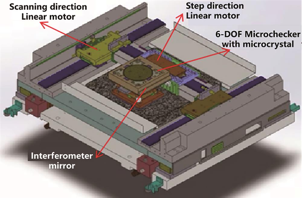
Fig. 1. Sketch diagram of step & scan projection lithography machine
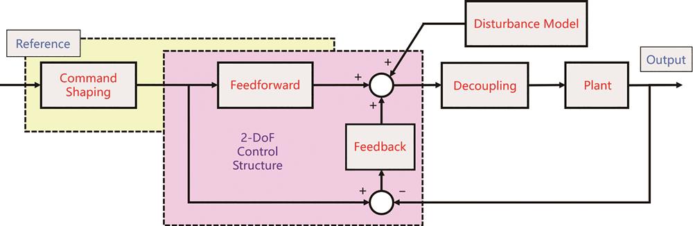
Fig. 2. Block diagram of advanced motion control system
Fig. 3. Basic block diagram of 6-DOF motion control system
Fig. 4. Block diagram of nonlinear feedback control system
Fig. 5. Block diagram of inverse model disturbance observer
Fig. 6. Horizontal step scanning trajectory of the wafer stage during lithography exposure
Fig. 7. Structure diagram of two DOF control system based on ILC. (a) Series structure; (b) parallel structure
Fig. 8. Sketch diagram of ILC compensation effect
Fig. 9. Control effects of ILC and IFFT with reference trajectory changes
Fig. 10. Two degrees of freedom motion control structure based on IFFT
Fig. 11. Control block diagram of micromotion following macromotion
Fig. 12. Control block diagram of macromotion following micromotion
Fig. 13. Block diagram of synchronous control between reticle stage and wafer stage
Fig. 14. Sketch diagram of trapezoidal velocity curve and third-order S-curve
Fig. 15. Sketch diagram of shaping technology design principle
Fig. 16. Flow chart of input shaping
Fig. 17. Structure sketch diagram of shaping technology application


Set citation alerts for the article
Please enter your email address

© Copyright 2018-2021 | Chinese Laser Press. All Rights Reserved 沪ICP备15018463号-20