• Photonics Research
  • Vol. 5, Issue 6, 629 (2017)
Tiecheng Wang1、2 and Xiangdong Zhang1、2、*
Author Affiliations
  • 1Beijing Key Laboratory of Nanophotonics & Ultrafine Optoelectronic Systems, School of Physics, Beijing Institute of Technology, 100081 Beijing, China
  • 2Kunming Institute of Physics, Kunming 650223, China
  • show less
    DOI: 10.1364/PRJ.5.000629 Cite this Article Set citation alerts
    Tiecheng Wang, Xiangdong Zhang. Improved third-order nonlinear effect in graphene based on bound states in the continuum[J]. Photonics Research, 2017, 5(6): 629 Copy Citation Text show less
    (a) Diagram of the sphere-graphene-slab structure and the TH generation process. The spheres are arranged in a square lattice with lattice constant a; the thickness of the dielectric slab is d, and the monolayer graphene is put at the interface between the monolayer dielectric spheres and the dielectric slab. When a plane wave with angular frequency ω is incident on the structure at the incident angle θi, the transmitted and reflected TH fields are generated due to the third-order nonlinear effect of graphene. Inset shows graphene layer with up medium denoted by 1 and down medium marked by 2. (b) Schematic of the degenerate FWM process in the three-layer structure. The pump beam at frequency ω1 and the probe beam at frequency ω2 are incident on the structure with arbitrary incident angles θ1 and θ2. Because of the third nonlinear effect of the graphene, the transmitted and reflected beams at FWM frequency ω3=2ω1−ω2 are generated with angle θ3. The angle θ3 is determined by the in-plane phase-matching condition.
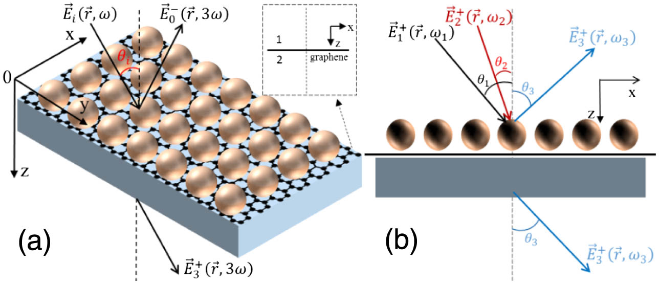
    Fig. 1. (a) Diagram of the sphere-graphene-slab structure and the TH generation process. The spheres are arranged in a square lattice with lattice constant a; the thickness of the dielectric slab is d, and the monolayer graphene is put at the interface between the monolayer dielectric spheres and the dielectric slab. When a plane wave with angular frequency ω is incident on the structure at the incident angle θi, the transmitted and reflected TH fields are generated due to the third-order nonlinear effect of graphene. Inset shows graphene layer with up medium denoted by 1 and down medium marked by 2. (b) Schematic of the degenerate FWM process in the three-layer structure. The pump beam at frequency ω1 and the probe beam at frequency ω2 are incident on the structure with arbitrary incident angles θ1 and θ2. Because of the third nonlinear effect of the graphene, the transmitted and reflected beams at FWM frequency ω3=2ω1ω2 are generated with angle θ3. The angle θ3 is determined by the in-plane phase-matching condition.
    (a) The absorption as a function of the wavelength λ when the Fermi energy is taken as Ef=0.23 eV (black line) and Ef=0.7 eV (red line). Inset shows the conductivity of the graphene. (b) The electric field distribution at the graphene location below the bottom of the spheres when the Fermi energy is taken as Ef=0.23 eV (black line) and Ef=0.7 eV (red line).
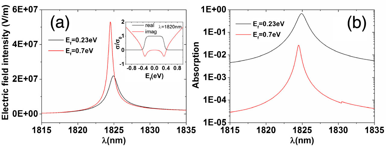
    Fig. 2. (a) The absorption as a function of the wavelength λ when the Fermi energy is taken as Ef=0.23  eV (black line) and Ef=0.7  eV (red line). Inset shows the conductivity of the graphene. (b) The electric field distribution at the graphene location below the bottom of the spheres when the Fermi energy is taken as Ef=0.23  eV (black line) and Ef=0.7  eV (red line).
    Transmitted (F1), reflected (F2), and total (F3) TH conversions in the three-layer structure and freestanding graphene as a function of the FF wavelength λ when the Fermi energy is taken as (a) Ef=0.23 eV and (b) Ef=0.7 eV. The TH enhancement G3 of TH signal in the three-layer structure compared with that in the freestanding graphene as a function of the FF wavelength λ for (c) different radius rs of the spheres or (d) various thickness d of the slab, the Fermi energy in (c) and (d) is taken as Ef=0.23 eV.
    Fig. 3. Transmitted (F1), reflected (F2), and total (F3) TH conversions in the three-layer structure and freestanding graphene as a function of the FF wavelength λ when the Fermi energy is taken as (a) Ef=0.23  eV and (b) Ef=0.7  eV. The TH enhancement G3 of TH signal in the three-layer structure compared with that in the freestanding graphene as a function of the FF wavelength λ for (c) different radius rs of the spheres or (d) various thickness d of the slab, the Fermi energy in (c) and (d) is taken as Ef=0.23  eV.
    TH enhancement of the (a) and (b) transmitted and (c) and (d) reflected TH beams as a function of the fundamental wavelength and the incident angle for S-(P) polarized pump beam. (e) and (f) show the absorption spectra of the three-layer structure. The bound states are denoted by S1, S2, and S3 (P1 and P2) for S-(P) polarized wave.
    Fig. 4. TH enhancement of the (a) and (b) transmitted and (c) and (d) reflected TH beams as a function of the fundamental wavelength and the incident angle for S-(P) polarized pump beam. (e) and (f) show the absorption spectra of the three-layer structure. The bound states are denoted by S1, S2, and S3 (P1 and P2) for S-(P) polarized wave.
    (a) Schematic of the FWM progress in the three-layer structure when all the waves are at the same wavelength; the incident angles of the pump and probe beams are 0° and θ, respectively; the angle of the generated FWM wave is equal to θ because of phase-match condition. (b) and (c) correspond to T and R of the transmitted and reflected FWM beams as a function of the FF wavelength and incident angle of the probe beam. The T and R in the three-layer structure and freestanding graphene as a function of the fundamental wavelength at θ=16.09° corresponding to the maxima when the Fermi energy is taken as (d) Ef=0.23 eV and (e) Ef=0.7 eV. The blue and pink lines show the absorption spectra under only one incident beam at the incident angles θ=0° and θ=16.09°, respectively.
    Fig. 5. (a) Schematic of the FWM progress in the three-layer structure when all the waves are at the same wavelength; the incident angles of the pump and probe beams are 0° and θ, respectively; the angle of the generated FWM wave is equal to θ because of phase-match condition. (b) and (c) correspond to T and R of the transmitted and reflected FWM beams as a function of the FF wavelength and incident angle of the probe beam. The T and R in the three-layer structure and freestanding graphene as a function of the fundamental wavelength at θ=16.09° corresponding to the maxima when the Fermi energy is taken as (d) Ef=0.23  eV and (e) Ef=0.7  eV. The blue and pink lines show the absorption spectra under only one incident beam at the incident angles θ=0° and θ=16.09°, respectively.
    Transmission (T) and reflection (R) as a function of the phase difference between the two parts of the pump beam with the same intensity.
    Fig. 6. Transmission (T) and reflection (R) as a function of the phase difference between the two parts of the pump beam with the same intensity.
    (a) Schematic of the FWM progress in the three-layer structure when the wavelengths of the pump and probe beams (λ1 and λ2) are not equal, the incident angles of the pump and probe beams are θ1=0° and θ2, respectively. (b) and (c) correspond to the transmitted and reflected FWM beams as a function of the wavelength λ1 and incident angle θ2 of the probe beam. The wavelength of the probe beam is taken as λ2=1760.29 nm.
    Fig. 7. (a) Schematic of the FWM progress in the three-layer structure when the wavelengths of the pump and probe beams (λ1 and λ2) are not equal, the incident angles of the pump and probe beams are θ1=0° and θ2, respectively. (b) and (c) correspond to the transmitted and reflected FWM beams as a function of the wavelength λ1 and incident angle θ2 of the probe beam. The wavelength of the probe beam is taken as λ2=1760.29  nm.
    T and R in the three-layer structure and freestanding graphene as a function of the wavelength λ1 with θ2=60°, which correspond to a peak when the Fermi energy is taken as (a) Ef=0.23 eV and (c) Ef=0.7 eV, respectively. (b) Blue and pink lines show the absorption as a function of the wavelengths of the pump or FWM beams (λ1 or λ3) under one incident beam at the incident angles 0° and θ3, respectively; the two relations are put together via phase match condition.
    Fig. 8. T and R in the three-layer structure and freestanding graphene as a function of the wavelength λ1 with θ2=60°, which correspond to a peak when the Fermi energy is taken as (a) Ef=0.23  eV and (c) Ef=0.7  eV, respectively. (b) Blue and pink lines show the absorption as a function of the wavelengths of the pump or FWM beams (λ1 or λ3) under one incident beam at the incident angles 0° and θ3, respectively; the two relations are put together via phase match condition.
    Tiecheng Wang, Xiangdong Zhang. Improved third-order nonlinear effect in graphene based on bound states in the continuum[J]. Photonics Research, 2017, 5(6): 629
    Download Citation