
Yin Shi, David R. Blackman, Ping Zhu, Alexey Arefiev, "Electron pulse train accelerated by a linearly polarized Laguerre–Gaussian laser beam," High Power Laser Sci. Eng. 10, 06000e45 (2022)
- High Power Laser Science and Engineering
- Vol. 10, Issue 6, 06000e45 (2022)
Abstract
1 Introduction
The construction of numerous high-power laser systems around the world[1–4] has enabled the development of novel particle (see reports of Bulanov et al.[5] and Esarey et al.[6] and references therein) and radiation sources[7–12] for multidisciplinary applications[13,14]. Most of the improvements of the laser beams used for driving laser–matter interactions have been focused on increasing power, on-target intensity, total energy and the contrast of the compressed pulse. For example, the proposed facility[3,4] that aims to cross the 100 PW limit is expected to be in development over the next decade. Concurrently, new optical techniques for producing helical wave-fronts[15–20] are also being developed. There now exist multiple computational[17,21–29] and experimental[15,18,30–32] studies examining interactions of helical laser beams with plasmas. There are also some published works on the terawatt scale helical laser production using a chirped-pulse amplification system[19,33]. Even though the techniques for creating helical beams with higher power are yet to be applied at high-power high-intensity laser facilities, they offer an exciting opportunity to create laser pulses with a qualitatively different field typology that can have a profound impact on laser–plasma interactions and particle acceleration.
There are several laser-based electron acceleration approaches with different degrees of maturity. The most frequently used ones are laser wakefield acceleration[6], which utilizes plasma electric fields, and direct laser acceleration[34], which relies on the fields of the laser for the energy transfer inside a plasma (e.g., see the report of Arefiev et al.[35]) or in vacuum[36]. These mechanisms are typically realized using conventional laser pulses. In an attempt to improve electron acceleration, several studies also considered radially polarized laser beams[37] and higher-order Gaussian beams[38]. Recently, there has been an increased interest in utilizing ultra-high-intensity laser beams with helical wave-fronts for electron acceleration in various setups, including vacuum acceleration[39–42], laser wakefield acceleration[43,44] and microstructural target electron acceleration[45].
Conventional high-power laser systems[1] generate linearly polarized (LP) laser beams without a twist to the laser wave-fronts, which prevents one from readily realizing the interactions utilizing ultra-high-intensity helical laser beams. The spatial structure of laser beams with helical wave-fronts can be viewed as a superposition of Laguerre–Gaussian (LG) modes, which is why these beams are often referred to as LG beams. An LG beam can potentially be produced from a standard LP Gaussian laser pulse in reflection from a fan-like structure[16,17,20]. This approach avoids transmissive optics and it is well-suited for generating high-power high-intensity LG beams at high efficiency. Achieving circularly polarized (CP) LG beams in conventional high-intensity laser systems is likely to be more challenging than achieving LP-LG beams, since a native Gaussian beam is LP and extra steps need to be taken to induce circular polarization. It is then imperative to study laser–plasma interactions involving LP-LG beams, as these beams are more likely to be achieved in the near-term at high-intensity laser systems such as ELI-NP[2] or the SG-II UP facility[46]. The focus of this paper is on electron acceleration in vacuum by an LP-LG laser beam following its reflection off a plasma with a sharp density gradient. This setup is sometimes referred to as the ‘reflection off a plasma mirror’[47], but we minimize the use of the term ‘plasma mirror’ to avoid any confusion with the optical shutters employed for producing high-contrast pulses. Direct laser acceleration in vacuum by a conventional laser beam is generally considered to be ineffective. The key issue is the transverse electron expulsion caused by the transverse electric field of the laser. The expulsion terminates electron energy gain from the laser and leads to strong electron divergence. It must be stressed that the expulsion is closely tied to the topology of the laser field, which is dominated by the transverse electric and magnetic fields. In two recent publications[39,40] we showed that a CP-LG beam with a properly chosen twist can be used to solve the expulsion problem. The wave-front twist creates a unique accelerating structure dominated by longitudinal laser electric and magnetic fields in the region close to the axis of the beam. The longitudinal electric field provides forward acceleration without causing electron divergence, while the longitudinal magnetic field provides transverse electron confinement. It was shown using 3D particle-in-cell (PIC) simulations that a CP-LG beam reflected off a plasma can generate dense bunches of ultra-relativistic electrons via the described mechanism[39,40]. The distinctive features of this acceleration mechanism are the formation of multiple sub-
Sign up for High Power Laser Science and Engineering TOC. Get the latest issue of High Power Laser Science and Engineering delivered right to you!Sign up now
In this paper, we present results of a 3D PIC simulation for a 600 TW LP-LG laser beam reflected off a plasma with a sharp density gradient. We find that, despite the loss of axial symmetry introduced by switching from circular to linear polarization, the key features of electron acceleration are retained. Namely, the laser is still able to generate dense ultra-relativistic electron bunches, with the acceleration performed by the longitudinal laser electric field in the region close to the laser axis. In the most energetic bunch, the electron energy reaches 0.29 GeV (10% energy spread). The bunch has a charge of 6 pC, a duration of approximately 270 as and remarkably low divergence of
Such dense attosecond bunches can find applications in research and technology[48,49], with one specific application being free-electron lasers[50]. The rest of this paper is organized as follows. Section 2 presents the field structure of the LP-LG beam and the setup of our 3D PIC simulation. Section 3 discusses the formation of electron bunches that takes place during laser reflection off the plasma. Section 4 examines the energy gain by the electron bunches during their motion with the laser pulse. Section 5 summarizes our key results and discusses their implication.
2 Field structure of the linearly polarized Laguerre–Gaussian beam and simulation setup
In this section, we present the structure of the LP-LG beam that we use in our 3D PIC simulation to generate and accelerate electron bunches. The section also presents the simulation setup.
The wave-front structure of a helical beam can be parameterized using two indices: the twist index
In our 3D PIC simulations, we use an LP 600 TW laser with
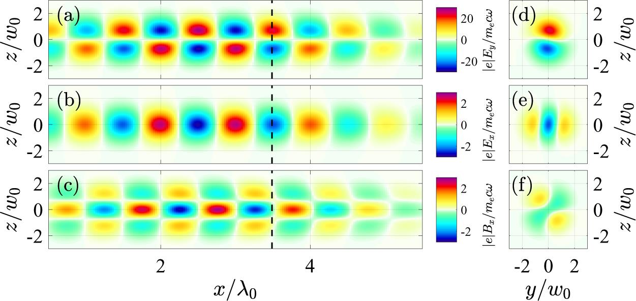
Figure 1.Electric and magnetic field components of an LP-LG laser beam before it encounters the plasma. Panels (a) and (d) show  ; panels (b) and (e) show
  ; panels (c) and (f) show
  . The left-hand column ((a)–(c)) shows the field structure in the
  -plane at
  . The right-hand column ((d)–(f)) shows the field structure in the
  -plane at the
  -position indicated with the dashed line in panels (a)–(c). All the snapshots are taken at
  fs from the simulation with parameters listed in Table
| Peak power (period averaged) | 0.6 PW |
| Radial and twist index | |
| Wavelength | |
| Pulse duration ( | |
| Focal spot size ( | |
| Location of the focal plane | |
| Laser propagation direction | |
| Polarization direction | |
| Position of the foil and the pre-plasma | |
| Density distribution of pre-plasma | |
| Electron and ion (C | |
| Gradient length | |
| Simulation box ( | 10 |
| Cell number ( | 800 cells |
| Macroparticles per cell for electrons | 100 at |
| Macroparticles per cell for C | 12 |
| Order of electromagnetic field solver | 4 |
Table 1. 3D PIC simulation parameters. Here,  m
m is the critical density corresponding to the laser wavelength
  . The initial temperatures for electrons and ions are set to zero.
It is instructive to compare the field structure of the LP-LG beam to the field structure of the CP-LG beam from Shi et al.[40]. In both cases, the longitudinal electric and magnetic fields peak on the axis of the beam where the transverse field vanishes. However, in contrast to the CP-LG beam, the longitudinal electric and magnetic fields of the LP-LG beam lack axial symmetry (see Figures 1(e) and 1(f)). The difference in symmetry can be illustrated by constructing an LP-LG beam (
As stated earlier, we want to contrast our results with those for a right-CP-LG beam that has the same power. The key player in electron acceleration is the longitudinal electric field of the laser, because it is this field that performs most of the acceleration for the electrons moving along the laser axis. We use the discussed decomposition for the LP-LG beam to compare the longitudinal field strength
In our simulation performed using the PIC code EPOCH[51], the discussed LP-LG beam is reflected off a plasma with a sharp density gradient. In what follows, we provide details of the simulation setup that we use in the next sections to study electron injection and acceleration. The target is initially set as a fully ionized carbon plasma with electron density
3 Electron injection into the linearly polarized Laguerre–Gaussian laser beam
In this section we discuss the formation of electron bunches that takes place during laser reflection off the plasma. We refer to this process as the ‘electron injection’, because, once the bunches are formed, they continue surfing with the laser beam.
Figure 2 shows various aspects of electron injection. All snapshots are taken at
![]()
Figure 2.Structure of electron bunches shortly after laser reflection off the plasma ( fs). (a) Electron density on a log-scale, with the color representing
  . The blue, red and green contours denote
  ,
,  and
and  , respectively. The dashed rectangle marks the third bunch, whose additional details are provided in the remaining panels. (b) Electron areal density
  in the third bunch. (c) Cell-averaged electron divergence angle
  in the third bunch. (d), (e) 3D rendering of the electron density in the third bunch using different viewpoints.
To examine this expectation and to provide additional insights into electron bunch dynamics, we performed detailed particle tracking for the third bunch. We distinguish three groups of electrons based on their transverse position within the bunch at
![]()
Figure 3.(a) Areal density of the electrons in the third bunch at time  fs. (b) Three groups of electrons (blue, green and red markers) selected from the third bunch at
  fs for tracking. The electrons in each group are selected randomly. (c) Transverse positions of the three groups of electrons from (b) at
  fs. (d)–(f) Trajectories of the three groups of electrons in the transverse plane over the duration of the simulation. The line color shows electron energy. The markers show the electron locations at
  fs. (g)–(i) Time evolution of the longitudinal position for the same three groups of electrons, with (g) showing ‘blue’ electrons, (h) showing ‘green’ electrons and (i) showing ‘red’ electrons. The line color shows electron energy.
Figures 3(d)–3(f) provide projections of electron trajectories onto the beam cross-section, where the color-coding is used to show electron energy along each trajectory. The markers correspond to the electron positions at
4 Electron energy gain in the linearly polarized Laguerre–Gaussian laser beam
In Section 2 we showed that the reflection of an LP-PG beam produces dense electron bunches. These bunches can move with the laser beam, gaining energy. In this section we examine this energy gain.
Figures 3(g)–3(i) show how the energy of electrons in each group from Figure 3(b) changes over time. The magnitude of the longitudinal electron velocity
Before we proceed with the analysis of the electron acceleration, we take a closer look at the reflected fields. Figure 4(a) shows the transverse electric field away from the axis (
![]()
Figure 4.Electric and magnetic fields after reflection of the LP-LG laser beam off the plasma. (a) Longitudinal profiles of the transverse electric field  (red curve) and longitudinal magnetic field
  (blue line) at
  fs. Here,
  is plotted along the axis of the beam (
 ,
,  ), whereas
  is plotted at an off-axis location (
 ,
,  ) where its amplitude has the highest value. (b) Frequency spectra of
  (red line) and
  (blue line) from panel (a).
The momentum gain of the electrons moving along the axis of the laser beam can then be obtained by integrating the momentum balance equation:
We obtain the terminal momentum gain by taking the limit of
One can understand the dependence on
We now take into account the expression for
In comparison to the acceleration by a CP-LG beam with the same power
Figure 5 provides information of the long-term electron acceleration in the 3D PIC simulation. Figure 5(a) shows the electron energy distribution as a function of
![]()
Figure 5.Result of the long-term electron acceleration in the reflected LP-LG laser beam close to the beam axis. (a) Electron energy distribution as a function of  at
at  fs for electrons with
  . The inset shows the third bunch that is marked with the dashed rectangle in the main plot. (b) Time evolution of the electron distribution over the divergence angle
  in the third bunch (
 ). (c) Time evolution of the electron energy spectrum in the third bunch. The black dashed curve is the prediction obtained from
  . The start time of the acceleration is used as an adjustable parameter. (d) Electron energy versus the divergence angle in the third bunch shown in the inset of panel (a).
Figures 5(b) and 5(c) show the time evolution of the divergence angle and electron energy within the third bunch (see the dashed rectangle and the inset in Figure 5(a)). After an initial stage that lasts about 80 fs, the distribution over the divergence angle reaches its asymptotic shape. It can be seen from the snapshot in Figure 5(b) (taken at
We find that the electron bunches retain noticeable asymmetry following their prolonged interaction with the laser beam. To illustrate the asymmetry, Figures 6(a) and 6(b) show the areal density
![]()
Figure 6.(a) Areal density  and (b) cell-averaged divergence angle
  in the cross-section of the third bunch at
  fs and
  . (c)–(e) Snapshots of the longitudinal electric field
  in the cross-section of the laser beam at
  ,
,  fs (c),
  ,
,  fs (d) and
  ,
,  fs (e). Here,
  is calculated using the analytical expression
  is the amplitude of
  at
at  ,
,  .
.
We conclude this section by providing additional parameters of the most energetic electron bunch (the third bunch) generated by the considered 600 TW LP-LG laser beam. The electron energy in the bunch is 0.29 GeV with a full width at half maximum (FWHM) of approximately
5 Summary and discussion
Using 3D PIC simulations, we have examined electron acceleration by a 600 TW LP-LG laser beam with
An important conclusion from our study is that the key features that were previously reported for a CP-LG beam[39,40] are retained in the case of an LP-LG laser beam. It is likely that experimentally it will be easier to generate a high-power LP-LG beam than a high-power CP-LG beam. This is because the laser beams at high-power laser facilities are LP. Changing the polarization introduces additional challenges and complications that our approach of using an LP-LG beam allows one to circumvent. We hope that this aspect will make it easier to perform a proof-of-principle experiment.
Even though there are key similarities, there are also differences in electron injection and acceleration between the cases of LP-LG and CP-LG beams. The injection into the LP-LG beam is more complex, leading to a formation of two side-lobes that accompany the on-axis bunch. The asymmetry of the longitudinal electric field causes the on-axis electron bunches to become asymmetric. In contrast to that, the bunches generated by a CP-LG beam are axisymmetrical. For two beams with the same power, the LP-LG beam has weaker on-axis electric and magnetic fields. The reduction in the field strength leads to a reduced energy gain, with the terminal electron energy being lower by roughly a factor of
Our mechanism relies on electrons becoming relativistic during the injection process. It is this feature that allows the injected electrons to surf with the laser pulse without quickly slipping from an accelerating phase into an adjacent decelerating phase. Since the longitudinal laser electric field plays a critical role in the injection process, its amplitude needs to be relativistic to generate relativistic injected electrons. A reduction of the incident laser power can thus degrade the mono-energetic spectra of the electron bunches by reducing the amplitude of the longitudinal field. To examine this aspect, we ran an additional simulation with a reduced incident power of 60 TW. Even though the laser still generates electron bunches in this case, the bunches are no longer mono-energetic. The peak energy is also noticeably lower than the value predicted by Equation (6). The underlying cause is most likely the inability of electrons to stay for a prolonged period of time in an accelerating phase.
In this work, we primarily focused on the most energetic (third) electron bunch. The considered laser pulse generates five distinct electron bunches. Their parameters are given in Table 3 of Appendix A. We want to point out that the front and tail of the considered laser pulse are steeper than what one would expect for a Gaussian pulse with the same FWHM, which was a deliberate choice made to reduce the size of the moving window and thus computational costs. The electrons must be relativistic during their injection, so that they can start moving with the laser beam without significant slipping. If this is not the case, then the mono-energetic feature discussed earlier might be hard to achieve. A dedicated study is required to determine the role of the temporal shape of the laser pulse and its overall duration. We anticipate that a longer laser pulse would produce a large number of ultra-relativistic electron bunches. For example, an 800 fs 600 TW LP-LG laser beam[46] contains roughly 300 cycles, so it has the potential to generate a similar number of bunches. Such a pre-modulated electron beam with high charge can potentially be used to generate coherent undulator radiation and to create a free-electron laser[50,53].
| Sim. No. | Cell size | Cell number | Macro-particles per cell | Order of electromagnetic |
|---|---|---|---|---|
| (window size is the same) | e ( | field solver | ||
| #1 | 1/40 | 200, 36, 24 | 2 | |
| #2 | 1/40 | 400, 72, 48 | 4 | |
| #3 | 1/50 | 200, 36, 24 | 4 | |
| #4 | 1/80 | 100, 18, 12 | 4 |
Table 2. Parameters used for the four simulations depicted in
| #1 | #2 | #3 | #4 | #5 | |
|---|---|---|---|---|---|
| 0.02–0.1 | 0.02–0.28 | 0.29 (10%) | 0.22 (6%) | 0.1 (15%) | |
| 0.95 | 0.88 | 1.5 | 0.64 | 0.92 | |
| 0.06 | 1.5 | 2.2 | 1.3 | 0.06 | |
| 1.4 | 8 | 9 | 6.8 | 0.7 | |
| 300 | 360 | 270 | 260 | 540 |
Table 3. Parameters of all five electron bunches at  = 261 fs.
References
[1] C. N. Danson, C. Haefner, J. Bromage, T. Butcher, J.-C. F. Chanteloup, E. A. Chowdhury, A. Galvanauskas, L. A. Gizzi, J. Hein, D. I. Hillier, N. Hopps, Y. Kato, E. Khazanov, R. Kodama, G. Korn, R. Li, Y. Li, J. Limpert, J. Ma, C. Nam, D. Neely, D. Papadopoulos, R. Penman, L. Qian, J. Rocca, A. Shaykin, C. Siders, C. Spindloe, S. Szatmári, R. Trines, J. Zhu, P. Zhu, J. Zuegel. High Power Laser Sci. Eng, 7, e54(2019).
[2] C. Radier, O. Chalus, M. Charbonneau, S. Thambirajah, G. Deschamps, S. David, J. Barbe, E. Etter, G. Matras, S. Ricaud, V. Leroux, C. Richard, F. Lureau, A. Baleanu, R. Banici, A. Gradinariu, C. Caldararu, C. Capiteanu, A. Naziru, B. Diaconescu, V. Iancu, R. Dabu, D. Ursescu, I. Dancus, C. Alexandru Ur, K. A. Tanaka, N. V. Zamfir. High Power Laser Sci. Eng., 10, e21(2022).
[3] Z. Bu, J. Xu, T. Xu, L. Ji, R. Li, Z. Xu. Plasma Phys. Control. Fusion, 60, 044002(2018).
[4] Z. Li, Y. Leng, R. Li. Laser Photon. Rev., 16, 2100705(2022).
[5] S. S. Bulanov, E. Esarey, C. B. Schroeder, S. V. Bulanov, T. Z. Esirkepov, M. Kando, F. Pegoraro, W. P. Leemans. Phys. Plasmas, 23, 056703(2016).
[6] E. Esarey, C. B. Schroeder, W. P. Leemans. Rev. Mod. Phys., 81, 1229(2009).
[7] T. Nakamura, J. K. Koga, T. Z. Esirkepov, M. Kando, G. Korn, S. V. Bulanov. Phys. Rev. Lett., 108, 195001(2012).
[8] C. P. Ridgers, C. S. Brady, R. Duclous, J. G. Kirk, K. Bennett, T. D. Arber, A. P. L. Robinson, A. R. Bell. Phys. Rev. Lett., 108, 165006(2012).
[9] L. L. Ji, A. Pukhov, I. Y. Kostyukov, B. F. Shen, K. Akli. Phys. Rev. Lett., 112, 145003(2014).
[10] D. J. Stark, T. Toncian, A. V. Arefiev. Phys. Rev. Lett., 116, 185003(2016).
[11] T. Wang, X. Ribeyre, Z. Gong, O. Jansen, E. d’Humières, D. Stutman, T. Toncian, A. Arefiev. Phys. Rev. Appl., 13, 054024(2020).
[12] R. Capdessus, M. King, D. Del Sorbo, M. Duff, C. P. Ridgers, P. McKenna. Sci. Rep., 8, 9155(2018).
[13] S. V. Bulanov, J. J. Wilkens, T. Z. Esirkepov, G. Korn, G. Kraft, S. D. Kraft, M. Molls, V. S. Khoroshkov. Phys.-Uspekhi, 57, 1149(2014).
[14] K. J. Weeks, V. N. Litvinenko, J. M. J. Madey. Med. Phys., 24, 417(1997).
[15] A. Leblanc, A. Denoeud, L. Chopineau, G. Mennerat, P. Martin, F. Quere. Nat. Phys., 13, 440(2017).
[16] Y. Shi, B. Shen, L. Zhang, X. Zhang, W. Wang, Z. Xu. Phys. Rev. Lett., 112, 235001(2014).
[17] A. Longman, R. Fedosejevs. Opt. Express, 25, 17382(2017).
[18] A. Longman, C. Salgado, G. Zeraouli, J. I. A. Naniz, J. A. Pérez-Hernández, M. K. Eltahlawy, L. Volpe, R. Fedosejevs. Opt. Lett., 45, 2187(2020).
[19] W. Pan, X. Liang, L. Yu, A. Wang, J. Li, R. Li. IEEE Photon. J., 12, 1(2020).
[20] E. Porat, S. Lightman, I. Cohen, I. Pomerantz. J. Opt., 24, 085501(2022).
[21] J. Vieira, R. M. M. Trines, E. P. Alves, R. A. Fonseca, J. T. Mendonça, R. Bingham, P. Norreys, L. O. Silva. Phys. Rev. Lett., 117, 265001(2016).
[22] X. Zhang, B. Shen, Y. Shi, X. Wang, L. Zhang, W. Wang, J. Xu, L. Yi, Z. Xu. Phys. Rev. Lett., 114, 173901(2015).
[23] J. Vieira, J. T. Mendonça, F. Quéré. Phys. Rev. Lett., 121, 054801(2018).
[24] Y. Shi, J. Vieira, R. M. G. M. Trines, R. Bingham, B. F. Shen, R. J. Kingham. Phys. Rev. Lett., 121, 145002(2018).
[25] L. B. Ju, C. T. Zhou, K. Jiang, T. W. Huang, H. Zhang, T. X. Cai, J. M. Cao, B. Qiao, S. C. Ruan. New J. Phys., 20, 063004(2018).
[26] X.-L. Zhu, M. Chen, S.-M. Weng, P. McKenna, Z.-M. Sheng, J. Zhang. Phys. Rev. Appl., 12, 054024(2019).
[27] V. Tikhonchuk, P. Korneev, E. Dmitriev, R. Nuter. High Energy Density Phys., 37, 100863(2020).
[28] R. Nuter, P. Korneev, I. Thiele, V. Tikhonchuk. Phys. Rev. E, 98, 033211(2018).
[29] D. R. Blackman, R. Nuter, P. Korneev, V. T. Tikhonchuk. Phys. Rev. E, 102, 033208(2020).
[30] A. Denoeud, L. Chopineau, A. Leblanc, F. Quéré. Phys. Rev. Lett., 118, 033902(2017).
[31] J. Y. Bae, C. Jeon, K. H. Pae, C. M. Kim, H. S. Kim, I. Han, W.-J. Yeo, B. Jeong, M. Jeon, D.-H. Lee, D. U. Kim, S. Hyun, H. Hur, K.-S. Lee, G. H. Kim, K. S. Chang, I. W. Choi, C. H. Nam, I. J. Kim. Results Phys., 19, 103499(2020).
[32] R. Aboushelbaya, K. Glize, A. F. Savin, M. Mayr, B. Spiers, R. Wang, N. Bourgeois, C. Spindloe, R. Bingham, P. A. Norreys. Phys. Plasmas, 27, 053107(2020).
[33] Z. Chen, S. Zheng, X. Lu, X. Wang, Y. Cai, C. Wang, M. Zheng, Y. Ai, Y. Leng, S. Xu, D. Fan. High Power Laser Sci. Eng., 10, e32(2022).
[34] P. Gibbon. Short Pulse Laser Interactions with Matter(2005).
[35] A. V. Arefiev, V. N. Khudik, A. P. L. Robinson, G. Shvets, L. Willingale, M. Schollmeier. Phys. Plasmas, 23, 056704(2016).
[36] G. V. Stupakov, M. S. Zolotorev. Phys. Rev. Lett., 86, 5274(2001).
[37] N. Zïam, M. Thévenet, A. Lifschitz, J. Faure. Phys. Rev. Lett., 119, 094801(2017).
[38] P. Sprangle, E. Esarey, J. Krall. Phys. Plasmas, 3, 2183(1996).
[39] Y. Shi, D. Blackman, D. Stutman, A. Arefiev. Phys. Rev. Lett., 126, 234801(2021).
[40] Y. Shi, D. R. Blackman, A. Arefiev. Plasma Phys. Control. Fusion, 63, 125032(2021).
[41] D. R. Blackman, Y. Shi, S. R. Klein, M. Cernaianu, D. Doria, P. Ghenuche, A. Arefiev. Commun. Phys., 5, 116(2022).
[42] K. H. Pae, C. M. Kim, V. B. Pathak, C.-M. Ryu, C. H. Nam. Plasma Phys. Control. Fusion, 64, 055013(2022).
[43] J. Vieira, J. T. Mendonça. Phys. Rev. Lett., 112, 215001(2014).
[44] G.-B. Zhang, M. Chen, C. B. Schroeder, J. Luo, M. Zeng, F.-Y. Li, L.-L. Yu, S.-M. Weng, Y.-Y. Ma, T.-P. Yu, Z.-M. Sheng, E. Esarey. Phys. Plasmas, 23, 033114(2016).
[45] L.-X. Hu, T.-P. Yu, Y. Lu, G.-B. Zhang, D.-B. Zou, H. Zhang, Z.-Y. Ge, Y. Yin, F.-Q. Shao. Plasma Phys. Control. Fusion, 61, 025009(2018).
[46] J. Zhu, J. Zhu, X. Li, B. Zhu, W. Ma, X. Lu, W. Fan, Z. Liu, S. Zhou, G. Xu, G. Zhang, X. Xie, L. Yang, J. Wang, X. Ouyang, L. Wang, D. Li, P. Yang, Q. Fan, M. Sun, C. Liu, D. Li, Y. Zhang, H. Tao, M. Sun, P. Zhu, B. Wang, Z. Jiao, L. Ren, D. Li, X. Jiao, H. Huang, Z. Lin. High Power Laser Sci. Eng, 6, e55(2018).
[47] M. Thévenet, A. Leblanc, S. Kahaly, H. Vincenti, A. Vernier, F. Quéré, J. Faure. Nat. Phys., 12, 355(2016).
[48] N. Schönenberger, A. Mittelbach, P. Yousefi, J. McNeur, U. Niedermayer, P. Hommelhoff. Phys. Rev. Lett., 123, 264803(2019).
[49] D. S. Black, U. Niedermayer, Y. Miao, Z. Zhao, O. Solgaard, R. L. Byer, K. J. Leedle. Phys. Rev. Lett., 123, 264802(2019).
[50] Z. Huang, Y. Ding, C. B. Schroeder. Phys. Rev. Lett., 109, 204801(2012).
[51] T. D. Arber, K. Bennett, C. S. Brady, A. Lawrence-Douglas, M. G. Ramsay, N. J. Sircombe, P. Gillies, R. G. Evans, H. Schmitz, A. R. Bell, C. P. Ridgers. Plasma Phys. Control. Fusion, 57, 113001(2015).
[52] U. Teubner, P. Gibbon. Rev. Mod. Phys., 81, 445(2009).
[53] J. P. MacArthur, A. A. Lutman, J. Krzywinski, Z. Huang. Phys. Rev. X, 8, 041036(2018).
[55] L. Allen, M. W. Beijersbergen, R. J. C. Spreeuw, J. P. Woerdman. Phys. Rev. A, 45, 8185(1992).


Set citation alerts for the article
Please enter your email address

© Copyright 2018-2021 | Chinese Laser Press. All Rights Reserved 沪ICP备15018463号-20