Guohui Li, Huihui Pi, Yanfu Wei, Bolin Zhou, Ya Gao, Rong Wen, Yuying Hao, Han Zhang, Beng S. Ong, Yanxia Cui, "Passivation of degradation path enables high performance perovskite nanoplatelet lasers with high operational stability," Photonics Res. 10, 1440 (2022)

Search by keywords or author
- Photonics Research
- Vol. 10, Issue 6, 1440 (2022)

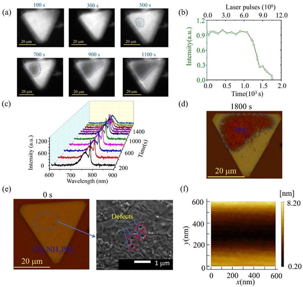
Fig. 1. (a) Microscopic image of an MAPbI 3 laser operating at a pump intensity of 1.1 P th (26.1 μJ / cm 2 ) after working for different times. (b) Lasing stability data of MAPbI 3 laser under femtosecond laser pumping with a repetition rate of 6 kHz in ambient air condition. (c) Spectrum evolution of MAPbI 3 laser operating at a pump intensity of 1.1 P th (26.1 μJ / cm 2 ) after working for different times. (d) Microscopic image of the nanoplatelet after operating for 1800 s. (e) Microscopic image and SEM image of the initial MAPbI 3 nanoplatelet with surface defects. (f) Atomic force microscopic image of the MAPbI 3 nanoplatelet shows that its RMS roughness is 2.1 nm.

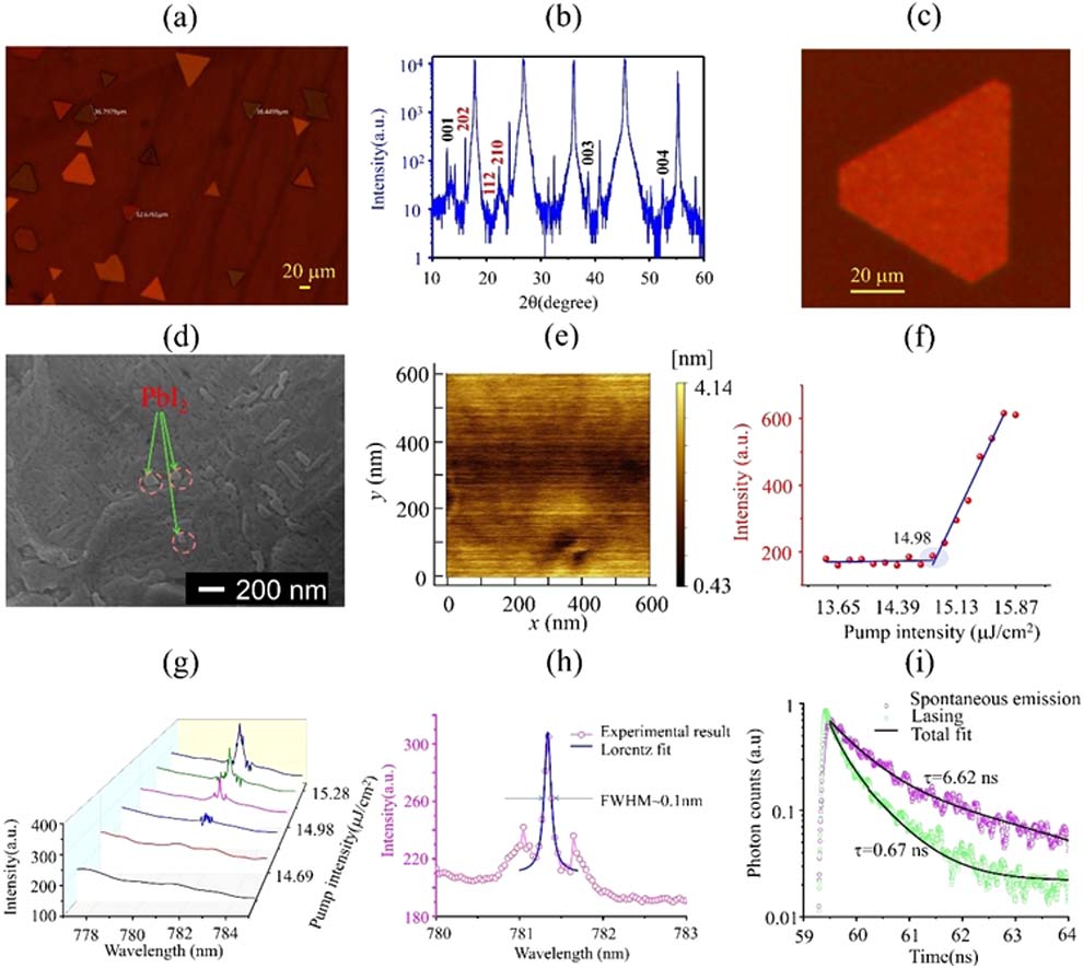
Fig. 2. (a) Microscopic image of MAPbI 3 nanoplatelets on a mica substrate. (b) XRD pattern of the MAPbI 3 nanoplatelets. (c) Microscopic image of an MAPbI 3 nanoplatelet used for demonstrating the laser before exposure to a pump laser. (d) SEM image of MAPbI 3 nanoplatelet. (e) AFM image of MAPbI 3 nanoplatelet shows its RMS roughness is ∼ 0.7 nm . (f) Laser output intensity as a function of pump intensity. (g) Evolution of emission spectra obtained at different pump intensities. (h) Lorentz fitting of a lasing oscillation mode at ≈ 781.3 nm gives an FWHM of 0.10 nm, corresponding to a Q factor of 7813. (i) Time-resolved photoluminescence (TRPL) spectra of perovskite nanoplatelet operating at spontaneous emission (P = 11.12 μJ / cm 2 ) and laser emission condition (P = 24.8 μJ / cm 2 ).

Fig. 3. (a) Microscopic images of a PbI 2 passivated MAPbI 3 nanoplatelet laser by operating at a pump intensity of 1.1 P th (16.48 μJ / cm 2 ) for different times. (b) Microscopic image of MAPbI 3 nanoplatelet after operating at 1.1 P th for 5600 s. (c) Lasing stability data of PbI 2 passivated MAPbI 3 nanoplatelet under femtosecond laser pumping with a repetition rate of 6 kHz in ambient air condition.

Fig. 4. (a) Schematic diagram of passivating the surface of MAPbI 3 nanoplatelet with DBP (C 64 H 36 ). (b) Process illustration of spin-coating a DBP film on the PbI 2 passivated MAPbI 3 nanoplatelet. (c) Laser output intensity as a function of pump intensity. (d) Evolution of emission spectra obtained at different pump intensities. (e) Lorentz fitting of a lasing oscillation mode at ≈ 779.9 nm , which gives an FWHM of 0.10 nm, corresponding to a Q factor of 7799. (f) Lasing stability data of the dual passivation processed MAPbI 3 nanoplatelet laser under the femtosecond laser pumping with a repetition rate of 6 kHz in ambient air condition. Dual passivation refers to PbI 2 passivation and DBP passivation.

Fig. 5. (a) Laser output intensity as a function of pump intensity. (b) Evolution of emission spectra obtained at different pump intensities. (c) TRPL spectra of a perovskite nanoplatelet without passivation operating at spontaneous emission (P = 17.87 μJ / cm 2 ) and laser emission condition (P = 26.81 μJ / cm 2 ).

Fig. 6. Lasing stability data of two other unpassivated MAPbI 3 lasers under femtosecond laser pumping with a repetition rate of 6 kHz in ambient air condition.

Fig. 7. Emission spectra of an unpassivated MAPbI 3 nanoplatelet laser after operating for different times measured using the ideaoptics PG2000 spectrometer (see Appendix A for more information).

Fig. 8. (a) AFM image of the edge of the unpassivated MAPbI 3 nanoplatelet and (b) the corresponding cross view showing the thickness.

Fig. 9. XRD patterns of MAPbI 3 nanoplatelets on mica substrate before and after exposure to the pump laser for 1800 s.

Fig. 10. Schematic diagram of the light path in an MAPbI 3 nanoplatelet.

Fig. 11. (a) Schematic diagram of an MAPbI 3 nanoplatelet on mica substrate being heated by a pump laser. (b) Transient thermal response of an MAPbI 3 nanoplatelet. (c) Temperature of an MAPbI 3 nanoplatelet at 290 fs after being pumped by a 290 fs laser pulse. (d) Radial temperature distribution of an MAPbI 3 nanoplatelet at 290 fs after being pumped by a 290 fs laser pulse.

Fig. 12. (a) AFM image of the edge of PbI 2 passivated MAPbI 3 nanoplatelet and (b) the corresponding thickness.

Fig. 13. Lasing stability data of another two PbI 2 passivated MAPbI 3 lasers under femtosecond laser pumping with a repetition rate of 6 kHz in ambient air condition.

Fig. 14. (a) Image of the PbI 2 passivated MAPbI 3 nanoplatelets encapsulated with a DBP film on mica substrate and (b) image of unpassivated MAPbI 3 nanoplatelets on mica substrate.

Fig. 15. Emission spectra of an unpassivated MAPbI 3 nanoplatelet laser and a DBP passivated MAPbI 3 nanoplatelet laser at the same pump intensity.

Fig. 16. Microscopic images of an MAPbI 3 nanoplatelet after leaving in ambient air condition for (a) 0 h and (b) 48 h, respectively.

Fig. 17. Microscopic images of the PbI 2 passivated MAPbI 3 nanoplatelets encapsulated with a DBP film after leaving in ambient air condition for different times.

Fig. 18. Lasing stability data of another two dual passivation processed MAPbI 3 lasers under femtosecond laser pumping with a repetition rate of 6 kHz in ambient air condition.

Fig. 19. Average operation time of unpassivated (sample A), PbI 2 passivated (sample B), and dual passivation processed nanoplatelet lasers (sample C) under femtosecond laser pumping with a repetition rate of 6 kHz in ambient air condition.

Set citation alerts for the article
Please enter your email address