• Opto-Electronic Advances
  • Vol. 4, Issue 3, 200045-1 (2021)
Qianbo Lu1、2、*, Yinan Wang3, Xiaoxu Wang3, Yuan Yao4, Xuewen Wang1、2, and Wei Huang1、2
Author Affiliations
  • 1Frontiers Science Center for Flexible Electronics (FSCFE), Shaanxi Institute of Flexible Electronics (SIFE) & Shaanxi Institute of Biomedical Materials and Engineering (SIBME), Northwestern Polytechnical University, Xi'an 710072, China
  • 2MIIT Key Laboratory of Flexible Electronics (KLoFE), Northwestern Polytechnical University, Xi’an 710072, China
  • 3The Key Laboratory of Information Fusion Technology, Ministry of Education, School of Automation, Northwestern Polytechnical University, Xi'an 710072, China
  • 4Wuhan National Laboratory for Optoelectronics-Huazhong University of Science and Technology, Wuhan 430074, China.
  • show less
    DOI: 10.29026/oea.2021.200045 Cite this Article
    Qianbo Lu, Yinan Wang, Xiaoxu Wang, Yuan Yao, Xuewen Wang, Wei Huang. Review of micromachined optical accelerometers: from mg to sub-μg[J]. Opto-Electronic Advances, 2021, 4(3): 200045-1 Copy Citation Text show less
    Typical specifications of potential application scenarios of MOEMS accelerometers.
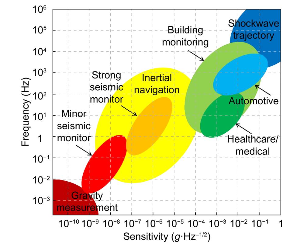
    Fig. 1. Typical specifications of potential application scenarios of MOEMS accelerometers.
    Summary of classification of MOEMS accelerometers showing their optical sensing units and figures of merit.
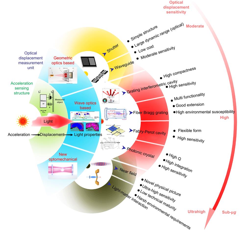
    Fig. 2. Summary of classification of MOEMS accelerometers showing their optical sensing units and figures of merit.
    Structure of a MOEMS accelerometer based on light intensity. Figure reproduced with permission from ref.8, IEEE.
    Fig. 3. Structure of a MOEMS accelerometer based on light intensity. Figure reproduced with permission from ref.8, IEEE.
    Simplified model of a MOEMS accelerometer based on light intensity. Figure reproduced with permission from ref.17, IEEE.
    Fig. 4. Simplified model of a MOEMS accelerometer based on light intensity. Figure reproduced with permission from ref.17, IEEE.
    (a) Schematic of a light intensity based MOEMS accelerometer by using waveguide. (b) Schematic view of the MOEMS accelerometer based on waveguide. Figure reproduced with permission from: (a) ref.18, Elsevier; (b) ref.19, Elsevier.
    Fig. 5. (a) Schematic of a light intensity based MOEMS accelerometer by using waveguide. (b) Schematic view of the MOEMS accelerometer based on waveguide. Figure reproduced with permission from: (a) ref.18, Elsevier; (b) ref.19, Elsevier.
    The experimental setup along with the mechanics.Figure reproduced with permission from ref.23, Springer Nature.
    Fig. 6. The experimental setup along with the mechanics.Figure reproduced with permission from ref.23, Springer Nature.
    Schematic of the MOEMS accelerometer. Figure reproduced with permission from ref.24, Springer Nature.
    Fig. 7. Schematic of the MOEMS accelerometer. Figure reproduced with permission from ref.24, Springer Nature.
    (a) Simplified model of a MOEMS accelerometer based on grating light valves. (b) Another MOEMS accelerometer based on grating light valve. Figure reproduced with permission from: (a) ref.29, AIP Publishing; (b) ref.48, IEEE.
    Fig. 8. (a) Simplified model of a MOEMS accelerometer based on grating light valves. (b) Another MOEMS accelerometer based on grating light valve. Figure reproduced with permission from: (a) ref.29, AIP Publishing; (b) ref.48, IEEE.
    Schematic of the grating interferometric cavity based accelerometer.Figure reproduced from ref.31, IEEE
    Fig. 9. Schematic of the grating interferometric cavity based accelerometer.Figure reproduced from ref.31, IEEE
    A modified phase-modulated grating.Figure reproduced with permission from ref.32, AIP Publishing.
    Fig. 10. A modified phase-modulated grating.Figure reproduced with permission from ref.32, AIP Publishing.
    (a) Differential detection method. (b) Another differential detection scheme. (c) Compensation scheme. (d) High symmetry design. (e) Closed-loop feedback scheme. (f) Modulation and demodulation scheme. Figure reproduced with permission from: (a) ref.33, (b) ref.34, (c) ref.39 and (f) ref.36, Optical Society of America; (d) ref.45, (e) ref.40, IEEE.
    Fig. 11. (a) Differential detection method. (b) Another differential detection scheme. (c) Compensation scheme. (d) High symmetry design. (e) Closed-loop feedback scheme. (f) Modulation and demodulation scheme. Figure reproduced with permission from: (a) ref.33, (b) ref.34, (c) ref.39 and (f) ref.36, Optical Society of America; (d) ref.45, (e) ref.40, IEEE.
    Simplified model of an FBG based accelerometer. Figure reproduced with permission from ref.47, IEEE.
    Fig. 12. Simplified model of an FBG based accelerometer. Figure reproduced with permission from ref.47, IEEE.
    (a) Schematic of a multi-point FBG based accelerometer. (b) Simplified model and physical picture of an FBG based accelerometer. Figure reproduced from: (a) ref.48, Optical Society of America; (b) ref.50, SPIE.
    Fig. 13. (a) Schematic of a multi-point FBG based accelerometer. (b) Simplified model and physical picture of an FBG based accelerometer. Figure reproduced from: (a) ref.48, Optical Society of America; (b) ref.50, SPIE.
    (a) A compact TFBG based accelerometer. (b) Another TFBG based accelerometer. Figure reproduced from: (a) ref.5 (b) ref.71, Optical Society of America.
    Fig. 14. (a) A compact TFBG based accelerometer. (b) Another TFBG based accelerometer. Figure reproduced from: (a) ref.5 (b) ref.71, Optical Society of America.
    An FBG based accelerometer with an additional buffer layer. Figure reproduced with permission from ref.75, Elsevier.
    Fig. 15. An FBG based accelerometer with an additional buffer layer. Figure reproduced with permission from ref.75, Elsevier.
    (a) Simplified model of an optical fiber unembedded FBG based accelerometer. (b) Schematic of an optical fiber unembedded FBG based accelerometer. (c) An optical fiber unembedded FBG based accelerometer. Figure reproduced with permission from: (a) ref.82 and (b) ref.78, IEEE; (c) ref.81, John Wiley and Sons.
    Fig. 16. (a) Simplified model of an optical fiber unembedded FBG based accelerometer. (b) Schematic of an optical fiber unembedded FBG based accelerometer. (c) An optical fiber unembedded FBG based accelerometer. Figure reproduced with permission from: (a) ref.82 and (b) ref.78, IEEE; (c) ref.81, John Wiley and Sons.
    A light-weight FBG based accelerometer. Figure reproduced with permission from ref.83, Elsevier.
    Fig. 17. A light-weight FBG based accelerometer. Figure reproduced with permission from ref.83, Elsevier.
    A miniature FBG vibration sensor. Figure reproduced with permission from ref.85, IEEE
    Fig. 18. A miniature FBG vibration sensor. Figure reproduced with permission from ref.85, IEEE
    Schematic of a Fabry-Perot cavity based accelerometer head. Figure reproduced with permission from ref.86, Optical Society of America.
    Fig. 19. Schematic of a Fabry-Perot cavity based accelerometer head. Figure reproduced with permission from ref.86, Optical Society of America.
    Schematic of a V-beam amplified Fabry-Perot cavity based accelerometer. Figure reproduced with permission from ref.96, Elsevier.
    Fig. 20. Schematic of a V-beam amplified Fabry-Perot cavity based accelerometer. Figure reproduced with permission from ref.96, Elsevier.
    Structure of a multidirectional Fabry-Perot cavity based accelerometer. Figure reproduced with permission from ref.113, IOP Publishing.
    Fig. 21. Structure of a multidirectional Fabry-Perot cavity based accelerometer. Figure reproduced with permission from ref.113, IOP Publishing.
    (a) Photograph and sketch of a Fabry-Perot accelerometer. (b) Structural configuration and photograph of a Fabry-Perot cavity based accelerometer. (c) Simplified model of an all-optical fiber vibration sensor. (d) A 45° Fabry-Perot interferometric cavity based accelerometer. Figures reproduced with permission from: (a) ref.103, AIP Publishing; (b) ref.130, IEEE; (c) ref.120, Optical Society of America; (d) ref.108, SPIE.
    Fig. 22. (a) Photograph and sketch of a Fabry-Perot accelerometer. (b) Structural configuration and photograph of a Fabry-Perot cavity based accelerometer. (c) Simplified model of an all-optical fiber vibration sensor. (d) A 45° Fabry-Perot interferometric cavity based accelerometer. Figures reproduced with permission from: (a) ref.103, AIP Publishing; (b) ref.130, IEEE; (c) ref.120, Optical Society of America; (d) ref.108, SPIE.
    An early demonstration of MOEMS accelerometer based on photonic crystal. Figure reproduced with permission from ref.138, IEEE.
    Fig. 23. An early demonstration of MOEMS accelerometer based on photonic crystal. Figure reproduced with permission from ref.138, IEEE.
    3D model of a photonic crystal based accelerometer. Figure reproduced with permission from ref.142, IEEE.
    Fig. 24. 3D model of a photonic crystal based accelerometer. Figure reproduced with permission from ref.142, IEEE.
    (a) Simplified model of a photonic crystal accelerometer along with (b) the working principle of ADF. Figure reproduced with permission from: (a, b) ref.141, IEEE.
    Fig. 25. (a) Simplified model of a photonic crystal accelerometer along with (b) the working principle of ADF. Figure reproduced with permission from: (a, b) ref.141, IEEE.
    SEM of the near-field MOEMS accelerometer based on vertically stacked sub-wavelength nano-gratings. Figure reproduced with permission from ref.149, Elsevier.
    Fig. 26. SEM of the near-field MOEMS accelerometer based on vertically stacked sub-wavelength nano-gratings. Figure reproduced with permission from ref.149, Elsevier.
    (a) Zoom-in of the zipper nanocavity region. (b) Schematic of the distorted zipper cavity showing the magnitude of the electric field. (c) False-coloured SEM image of the typical optomechanical accelerometer. Figure reproduced with permission from ref.150, Springer Nature.
    Fig. 27. (a) Zoom-in of the zipper nanocavity region. (b) Schematic of the distorted zipper cavity showing the magnitude of the electric field. (c) False-coloured SEM image of the typical optomechanical accelerometer. Figure reproduced with permission from ref.150, Springer Nature.
    (a) Scanning electron micrograph along with the finite element model of the optical resonance of the optomechanical sensor (b) Sketch of the optomechanical sensor and the zoom-in SEM image showing the active part designed (c) A chip-scale optomechanical inertial sensor based on surface plasmon coupling. Figure reproduced with permission from: (a) ref.154 and (b) ref.155, Springer Nature; (c) ref.156, John Wiley and Sons.
    Fig. 28. (a) Scanning electron micrograph along with the finite element model of the optical resonance of the optomechanical sensor (b) Sketch of the optomechanical sensor and the zoom-in SEM image showing the active part designed (c) A chip-scale optomechanical inertial sensor based on surface plasmon coupling. Figure reproduced with permission from: (a) ref.154 and (b) ref.155, Springer Nature; (c) ref.156, John Wiley and Sons.
    Schematics of different setups for light-matter interaction based detection. (a) A cavity with a microdisk trapped by a light field, which is cooled for a readout by a second light field166. (b) An optomechanical cavity with an injected light field and an elastic mechanical mirror164. (c) An optomechanical system with a trapped and laser-cooled nanodiamond165. (d) A ring cavity comprising three tilted mirrors167. Figure reproduced with permission from: (a) ref.166 and (b) ref.164, America Physical Society; (c) ref.165, Springer Nature; (d) ref.167, John Wiley and Sons.
    Fig. 29. Schematics of different setups for light-matter interaction based detection. (a) A cavity with a microdisk trapped by a light field, which is cooled for a readout by a second light field166. (b) An optomechanical cavity with an injected light field and an elastic mechanical mirror164. (c) An optomechanical system with a trapped and laser-cooled nanodiamond165. (d) A ring cavity comprising three tilted mirrors167. Figure reproduced with permission from: (a) ref.166 and (b) ref.164, America Physical Society; (c) ref.165, Springer Nature; (d) ref.167, John Wiley and Sons.
    (a) Experimental setup of the ultra-sensitive optomechanical system proposed. (b) An atom-chip based accelerometer setup and space-time trajectories. Figure reproduced with permission from: (a) ref.168, The American Association for the Advancement of Science; (b) ref.169, America Physical Society.
    Fig. 30. (a) Experimental setup of the ultra-sensitive optomechanical system proposed. (b) An atom-chip based accelerometer setup and space-time trajectories. Figure reproduced with permission from: (a) ref.168, The American Association for the Advancement of Science; (b) ref.169, America Physical Society.
    ParameterGeometric optics basedWave optics basedNew optomechanical
    Grating interferometric cavity basedFiber Bragg grating basedFabry-Perot cavity basedPhotonic crystal
    Optical displacement resolutionμm~nm scalesub-nmnm scalenm~pm scalesub-nmup to fm level
    Noise equivalent accelerationmg·Hz–1/2~ng·Hz–1/2 (depend on mechanical design) μg·Hz–1/2~ng·Hz–1/2sub-μg·Hz–1/2μg·Hz–1/2~ng·Hz–1/2sub-μg·Hz–1/2up to sub-ng·Hz–1/2
    CharacteristicsSimple structure, low cost, moderate sensitivityHigh compactness, high sensitivityMulti functionality, moderate sensitivityFlexible form, high sensitivityHigh integration, high sensitivityUltra-high sensitivity
    Scope of applicationsDaily applications to geophysical applicationsInertial navigation, geophysical applicationsDaily applications, infrastructure monitoringInertial navigation, geophysical applicationsInertial navigationInertial navigation, geophysical applications
    Table 1. Typical specifications of various MOEMS accelerometers along with their characteristics and applications
    Qianbo Lu, Yinan Wang, Xiaoxu Wang, Yuan Yao, Xuewen Wang, Wei Huang. Review of micromachined optical accelerometers: from mg to sub-μg[J]. Opto-Electronic Advances, 2021, 4(3): 200045-1
    Download Citation