
Qianbo Lu, Yinan Wang, Xiaoxu Wang, Yuan Yao, Xuewen Wang, Wei Huang. Review of micromachined optical accelerometers: from mg to sub-μg[J]. Opto-Electronic Advances, 2021, 4(3): 200045-1
- Opto-Electronic Advances
- Vol. 4, Issue 3, 200045-1 (2021)
Abstract
Keywords
Introduction
As graduations of a scale for acceleration, velocity and position measurement, accelerometer is not only a key component of the inertial navigation system, but also plays a vital role in a broad spectrum of applications such as automobile safety, earthquake monitoring, gravity detection, heading indication, attitude reference. With the rapid development of microelectronics and micro-manufacturing technology, high performance and highly integrated MEMS accelerometers have become a big class of accelerometers, which covers the applications in consumer electronics, industry, medical treatment, etc. Due to the growing demand for higher performance and greater functionality, MOEMS accelerometers emerged at the right moment, combining the advantages of optical detection and traditional MEMS accelerometers. Compared to conventional MEMS accelerometers, MOEMS accelerometers are usually with advanctages of high precision, fast response, resistance to electromagnetic interference, and the ability to work in harsh environments. Therefore, they show promise for broad application prospect in inertial navigation, geophysics and other fields that require high sensitivity and precision, and are also the trend of future accelerometers development.
Various MOEMS accelerometers have been reported in past decades, yet a systematical review of the MOEMS accelerometers has remained elusive. In this review, we mainly focus on the measurement principle and performance of state-of-the-art MOEMS accelerometers, and divide them into several categories according to the optical measurement principle. By taking typical demonstrations as examples, the merits and disadvantages are presented here, thereby drawing a big picture for MOEMS accelerometers, along with their application prospect and development tendency.
Requirement analysis of MOEMS accelerometers
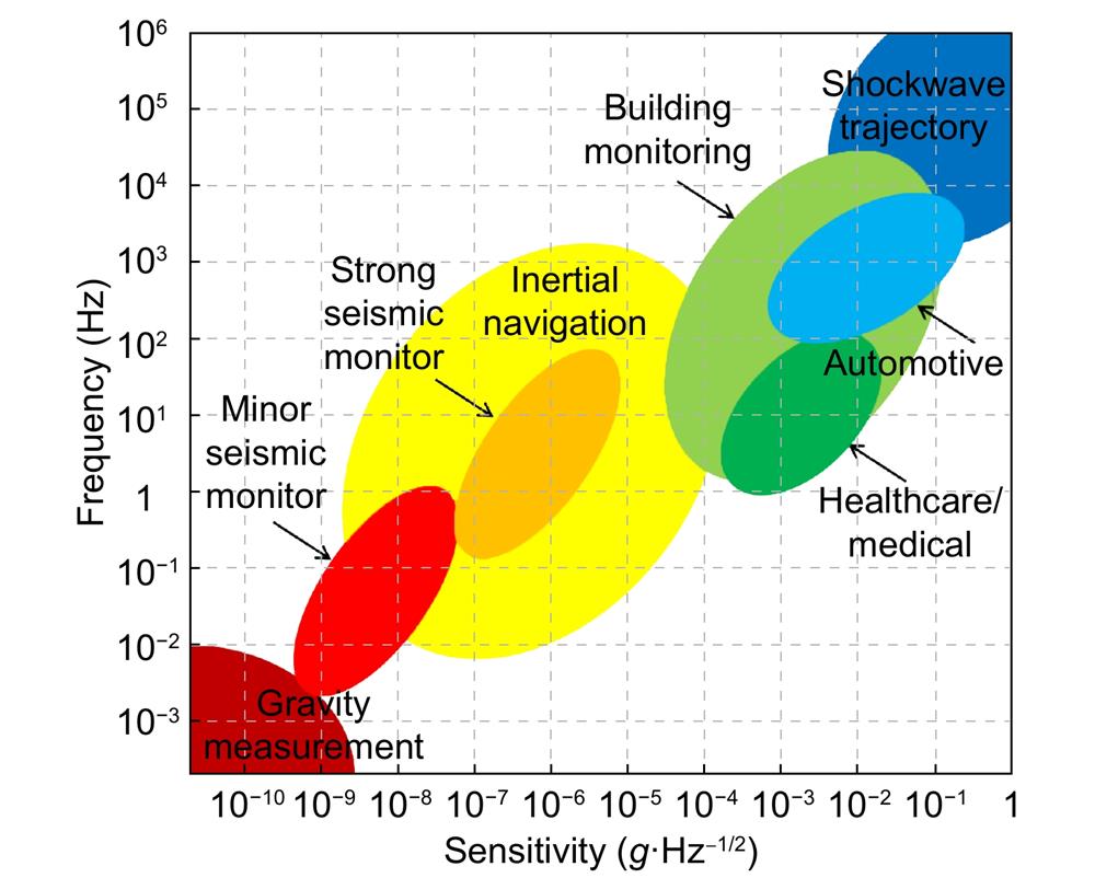
The application of MOEMS accelerometers spans a wide variety of areas, while different application scenarios have different requirements on performances. As illustrated in Fig. 1, for example, microgravity detection
![]()
Figure 1.
Application of inertial navigation
Based on Newtonian mechanics law, the inertial navigation system measures the acceleration and angular acceleration of the carrier, taking the time integral and then transforms the obtained data into the navigation coordinate system to obtain the velocity, yaw angle and position information. Accelerometer is one of the key components of the inertial navigation system. The working environment of inertial navigation system includes air, ground and underwater, which requires the accelerometer to have a strong anti-environment disturbance ability. For inertial guidance long-range missiles, 70% of the precision depends on the guidance system. This poses a significant challenge for the accelerometer to feature an excellent acceleration measurement precision and zero bias stability. Also, the size of the inertial navigation system as well as the accelerometer should be considered due to the limited carrying capacity of various aircrafts and underwater vehicles. Because of the advantages of high precision, small size and anti-electromagnetic interference, MOEMS accelerometers have good prospects for the application of inertial navigation.
Application of building monitoring
Small deformation would cause cracks or other catastrophic losses in structures such as buildings and bridges. Accelerometer can help detect flaws and give early warning by measuring the vibration of buildings, thus, playing a key role in the building monitoring system. There are some limitations of traditional accelerometers in such applications due to their complicated wiring, difficulty in multi-point measurement and electromagnetic susceptibility. As a comparison, MOEMS accelerometers have strong anti-electromagnetic disturbance ability and higher precision, and some types of MOEMS accelerometers such as fiber grating based accelerometers can realize long-distance and distributed measurement, which helps to break through these limitations
Geophysical applications
Geophysical applications mainly contain seismic, drilling process monitoring, resource exploration, monitoring of earth tides and volcanic activity, etc. The seismic monitoring, which can be further divided into minor and strong seismic monitoring, requires a noise level of better than 1
Daily applications
Automotive electronics
In the field of automotive electronics, typical applications including airbag, anti-skid brake system, electric suspension, navigation control all require acceleration measurement. Automotive electronics applications usually do not need a high precision but have a high demand for size and cost. Thus, several MOEMS accelerometers with simple structure and low cost, such as light intensity based accelerometers, can be well applied in such scenes.
Movement monitoring
Motion monitoring makes use of the output value of the accelerometer to build the connection between the output and the daily exercise of human body, such as sitting, standing, running, jumping, and cycling with the help of skin temperature, heart rate and other information obtained from different sensors. This helps to provide professional training assistance and guidance for the subjects, so as to achieve accurate adjustment of training volume and intensity. Due to the long running time, the accelerometers are required to feature good long-term stability and low power consumption.
Medical diagnosis
Accelerometers can be used to assist diagnosis and treatment of patients with motor disorders or joint problems. Similar to motion monitoring, this kind of application puts requirements on accelerometer with good ductility and long-term stability, as well as low power consumption. Optical fiber based MOEMS accelerometers which are adapted to different environmental conditions might be feasible in this application.
Different MOEMS accelerometer types
As shown in Fig. 2, a MOEMS accelerometer usually consists of an acceleration sensing structure and an optical displacement measurement unit. The former is to convert the applied acceleration to a displacement, whereas the latter one is to detect the displacement. The performance of two parts determine the overall performance of the accelerometer together. In this paper, the MOEMS accelerometers are broadly divided in three categories according to the principles of optical displacement measurement unit.
![]()
Figure 2.
Since the birth of the first optical accelerometer
Geometric optics based MOEMS accelerometers
Principle
Geometric optics based MOEMS accelerometer is a kind of accelerometer which senses the displacement or acceleration by directly modulating the radiation intensity of light. As it is subject to acceleration, the proof mass in the accelerometer generates an inertia displacement, which directly changes the output light intensity. In conjunction with the acceleration-displacement sensitivity of the acceleration sensing structure, it is able to calculate the magnitude of the input acceleration. This kind of MOEMS accelerometer has advantages of simple structure and low cost, but it is usually difficult to guarantee its precision due to the relatively high susceptibility to the fluctuation of incident light source and external environment.
Light-intensity based accelerometers
One of the first reported geometric optics based accelerometer was proposed by Abbaspour-Sani et al.
![]()
Figure 3.
Except the grating shutter, waveguides can also be exploited to serve as the light intensity modulation component of an accelerometer. In 2004, Plaza et al.
![]()
Figure 4.
![]()
Figure 5.(
It can be seen that most of the light intensity based accelerometers hold a simple light path and low sensitivity, but there still are several avenues to improve the sensitivity. For example, as what conventional MEMS accelerometers did
![]()
Figure 6.
Similarly, Tu et al.
![]()
Figure 7.
To sum up, the MOEMS accelerometers based on geometric optics are capable of achieving simple structure and low cost measurement of acceleration, because no high requirements for light sources and detectors are involved. Nevertheless, the measurement, especially the optical displacement measurement unit, would be significantly affected by the fluctuation of the light source and environmental factors. Thus, this type of MOEMS accelerometer has some limitations in high precision acceleration measurement even though there is some room to modify the mechanical sensing unit.
Wave optics based MOEMS accelerometers
Principle
The optical displacement measurement unit of a wave optics based accelerometer is based on the wave aspect of light. When the accelerometer is subjected to an external acceleration, the inertia force leads to a displacement of the proof mass, which causes the wavelength (or frequency/phase) change. By detecting the corresponding change, the displacement and the input acceleration can be obtained with relatively higher sensitivity due to the accurate scale of the wavelength compared with the amplitude of light. According to the form and measuring principle of the optical displacement measurement unit, the MOEMS accelerometers of wave optics are subdivided into grating interferometric cavity, FBG, Fabry-Perot cavity and photonic crystal, etc.-based categories.
Grating interferometric cavity scheme
Regarding the grating interferometric cavity based accelerometers, the core sensing unit is a cavity of grating interferometer. It is a kind of micro cavity that is composed of a movable diffraction grating (or grating light valve). The variation of the cavity length changes the intensity of the emitted light by modulating the optical path difference. Taking the wavelength as the ruler, the grating interferometric cavity is able to achieve the sub-nanometer scale precision, thus, paves the way for the higher precision acceleration measurement. Moreover, this type of MOEMS accelerometer has compact optical path and setup, so it also has advantages in miniaturization and integration.
At the end of last century, Cooper et al.
![]()
Figure 8.(
Hall et al.
![]()
Figure 9.
![]()
Figure 10.
At the same time, the grating interferometric cavity based accelerometer also derived a lot of improved demonstrations. The measuring principle improving schemes include advanced higher interference diffraction order scheme
![]()
Figure 11.(
In summary, the grating interferometric cavity based accelerometer is one type of the accelerometers based on the wave aspect of light. They were born at the end of last century and developed at the beginning of this century. The technology maturity and performances have been exceedingly improved over the past two decades. By optimizing the structure, introducing phase modulation and various subdivision means, the NEA of interferometric cavity based accelerometers can universally break through 1
Fiber Bragg grating scheme
The optical displacement measurement unit of the FBG based accelerometers is, namely, a Fiber Bragg Grating. When an external acceleration is applied, the inertia displacement of the proof mass produces the strain of the FBG, and changes the wavelength of the output light under the effect of strain. By detecting the wavelength variation, the acceleration can be obtained. FBG based accelerometer is a kind of MOEMS accelerometers which is widely studied and applied extensively at present because of its unique advantages such as good ductility and multi-point measurement ability. The measurement principle, performances, advantages and disadvantages of several kinds of FBG based accelerometers are reviewed below.
In 1996, Kersey et al.
![]()
Figure 12.
FBG based accelerometer is a good candidate for the building and infrastructure monitoring due to its capability of multi-point measurement. For example, Linze et al.
![]()
Figure 13.(
FBG based accelerometers
Most recently, more attention has been paid to improve the performances of FBG based accelerometers. Obviously, sensitivity is an important parameter for the FBG based accelerometers, so that many attempts and theoretical studies have been made to improve it
Regarding the design of fiber, Tilted Fiber Bragg Grating (TFBG) is a special FBG to be pointed out, which can efficiently couple the light between the core mode and cladding modes
![]()
Figure 14.(
Some others used novel mechanical design to increase the sensitivity of FBG based accelerometers
![]()
Figure 15.
Birefringence splitting of FBG reflection peak mainly contributed by fiber embedding should be avoided because it would degrade the performance of the optical readout, and further the accelerometer. There are a lot of attempts in order to address this issue
![]()
Figure 16.(
Weight is another factor to consider in the applications of FBG based accelerometers. In 2018, Galv et al.
![]()
Figure 17.
![]()
Figure 18.
In general, the FBG based accelerometers measure the stress, strain, and thus the acceleration through the variation of the Bragg wavelength. This type of MOEMS accelerometer has received the most extensive attention over the past 30 years, and extends its application from the basic single-point acceleration measurement to the practical use such as building health monitoring. Regarding the performances, the sensitivity is pushed forward from the NEA of around
The advantages of resistance to electromagnetic interference, low loss, good extension, small volume, and light weight enable the applications of FBG based accelarometer in the complex environment. In addition, the multiplexed FBG based accelerometers provide an effective solution for the implementation in large infrastructures. However, FBG is vulnerable to the influence of ambient temperature and is difficult to compensate. Furthermore, the detection of the wavelength usually requires a complicated readout, which makes the integration difficult.
Fabry-Perot cavity scheme
Fabry-Perot cavity is another candidate of optical displacement measurement unit for a MOEMS accelerometer. As it is subject to acceleration, the inertial force of the proof mass drives the end face of the cavity, changing the reflection or transmission spectrum. By analyzing the spectrum, the magnitude of the input acceleration can be obtained. For MOEMS accelerometers, fiber is always employed to construct a compact Fabry-Perot cavity because its end surface is a natural candidate for a component of the cavity. Herein we review several types of Fabry-Perot cavity based accelerometers, including their principles and performances.
Figure 19 shows an early demonstration of the Fabry-Perot cavity based accelerometer, which is proposed by Gerges
![]()
Figure 19.
In recent years, many attempts have been made to further improve the sensitivity without compromising other performances by means of mechanical design
Mechanical amplification is an effective way to improve the sensitivity. For example, Davies et al.
![]()
Figure 20.
Cavity optomechanics
There are expensive efforts put in improving other performances apart from the sensitivity. Someone tried to perform multi-axis detection in one accelerometer
![]()
Figure 21.
Other researchers tried to combine the optical fiber with the Fabry-Perot cavity to construct high multifunctional sensors, which are capable of detecting a wide range of physical parameters such as dynamic strain
![]()
Figure 22.(
In recent decades, Fabry-Perot cavity based accelerometers have gained increased attention due to their high sensitivity, compact structure, and simple optical path. The theoretical performances of the Fabry-Perot cavity based accelerometer could be very high, for example, the improved noise equivalent displacement of the optical displacement sensing unit can reach as low as 10-14
Photonic crystal scheme
For photonic crystal based accelerometers, the optical displacement sensing measurement unit is usually a one- or two-dimensional photonic crystal waveguide. Photonic crystals have photonic band gap, which has a selectivity for the wavelength of the light propagating in. The external acceleration deforms the periodic photonic structure, thus breaking and changing the selectivity. The acceleration is obtained by detecting the variation of wavelength (or other properties of light). Photonic crystal accelerometers usually have a large bandwidth due to their high Q value, and they also have high device compactness. Herein we present the principles, properties, advantages and disadvantages of several typical demonstrations of photonic crystal based accelerometers.
In 2004, Jaksic et al.
![]()
Figure 23.
Photonic crystal structures include one-
![]()
Figure 24.
The same author also designed a two-dimensional photonic crystal accelerometer based on wavelength modulation
Currently, the research about photonic crystal based accelerometers is gaining rising attention and rapid development
![]()
Figure 25.(
Summary of wave optics based accelerometers
As mentioned earlier, MOEMS accelerometers based on the principle of wave optics can generally improve the performances, especially the sensitivity, when compared to the geometric optics based accelerometers. They can be well adapted to different applications due to the various forms. Among them, the grating interferometric cavity based accelerometer is a MOEMS accelerometer with a relatively high precision, and the NEA can easily reach down to 100
New optomechanical accelerometer
Aforementioned MOEMS accelerometers based on geometric optics and wave optics have relatively high precisions, large dynamic ranges, as well as electrical insulating properties due to the advantages of the optical displacement measurement unit, and can be applied to many application scenes. However, regarding the propagation characteristics of light, these two kinds of MOEMS accelerometers both make approximations to some degrees, which not only provide an inaccurate interpretation of the nanoscale optical effects, but also lose the high-frequency information in the near-field. In order to break through the sensitivity limit of the MOEMS accelerometer, for example, approaching or even exceeding the SQL, researchers experimented with light field manipulation in scale of sub-wavelength and utilization of light-matter interaction, to push the sensitivity beyond the state of the art.
Taking advantages of surface plasmon
In 2012, Painter et al.
![]()
Figure 26.
![]()
Figure 27.(
Other forms of surface plasmon based cavity also proved themselves as potential candidates of ultra-sensitive optical displacement readout with high compactivity. For example, Kim
![]()
Figure 28.(
There are still several demonstrations of practical MOEMS accelerometers based on surface plasmon coupling by means of nanocavity or nanostructure, such as the designs proposed by Rogers
The light-matter interaction of the optomechanical cavity receives extensive attention over the past decades, and it is the other avenue to realize the ultra-sensitive acceleration measurement, which has been identified as one of the most effective gravity estimation methods
Underpinned with the quantum investigation of the theoretical effectiveness of measuring acceleration through light-matter interaction
![]()
Figure 29.
![]()
Figure 30.(
The underlying idea of the light-matter interaction, or more specifically, the cavity optomechanics is not the topic of this review. Ones could refer to ref.
To sum up, the research of new optomechanical MOEMS accelerometers has been accelerating rapidly since its birth in the new century. This type of MOEMS accelerometer surpasses the limitation of scalar diffraction theory in terms of the measurement principle. By extracting the high frequency information of the near-field or quantum states through the light-matter interaction, the accelerometer is able to approach or exceed the SQL. A variety of new demonstrations are constantly emerging while the researchers pay more attention to the breakthrough of the measurement principle at present and try to draw the physical picture of the nano-scale behind the phenomenon. As a result, the technology maturity is generally not high, and most of the demonstrations remain just a proof-of-principle, which is far from being implemented in applications. In the future, the new optomechanical MOEMS accelerometers will pursue both the innovation of the mechanism and design, as well as the technical feasibility and maturity, which cannot only push forward the theoretical performances, but can also strive to translate the advanced principle to the advanced technology and devices to meet the rising requirements.
Conclusion and prospect
MOEMS accelerometers have progressed significantly since the first demonstration was reported in 1980s. By taking the advantages of both the MEMS and optical sensing technologies, MOEMS accelerometers are now capable of achieving impressive level of performances. This paper first analyzes practical and potential demands of applications for MOEMS accelerometers, and then roughly divides the accelerometers into three main categories in terms of the optical sensing principle. The performances, especially the sensitivity, are generally increasing from the geometric optics based, to wave optics based, and finally to the new optomechanical accelerometers, as listed in Table 1. However, it should be noted that each category has its own merits and demerits, which are adapted to different requirements. Also, not all applications require extremely high sensitivity or precision. For example, the geometric optics based accelerometers usually have a relatively simple structure and low cost, one can routinely measure mg scale accelerations in daily applications by using this type of accelerometer. The wave optics based accelerometers are extensively studied and contain a lot of sub-categories, and some are able to provide μg performance adapted to applications such as inertial navigation, while some specialize in other performances such as multi-point and multi-axis measurement. The new optomechanical accelerometers have been demonstrated to hold the promise of realizing ultra-high sensitivity, which can approach or even being pushed beyond the SQL. However, they are not yet ripe, let alone enter the large-scale application stage.
| Parameter | Geometric optics based | Wave optics based | New optomechanical | |||
| Grating interferometric cavity based | Fiber Bragg grating based | Fabry-Perot cavity based | Photonic crystal | |||
| Optical displacement resolution | μm~nm scale | sub-nm | nm scale | nm~pm scale | sub-nm | up to fm level |
| Noise equivalent acceleration | mg·Hz–1/2~ng·Hz–1/2 (depend on mechanical design) | μg·Hz–1/2~ng·Hz–1/2 | sub-μg·Hz–1/2 | μg·Hz–1/2~ng·Hz–1/2 | sub-μg·Hz–1/2 | up to sub-ng·Hz–1/2 |
| Characteristics | Simple structure, low cost, moderate sensitivity | High compactness, high sensitivity | Multi functionality, moderate sensitivity | Flexible form, high sensitivity | High integration, high sensitivity | Ultra-high sensitivity |
| Scope of applications | Daily applications to geophysical applications | Inertial navigation, geophysical applications | Daily applications, infrastructure monitoring | Inertial navigation, geophysical applications | Inertial navigation | Inertial navigation, geophysical applications |
Table 1. Typical specifications of various MOEMS accelerometers along with their characteristics and applications
In the following decades, the community of MOEMS accelerometer will continue to flourish, while much effort would be expended to collaborative design for both optical and mechanical components, improvement of the technological maturity, as well as advance precision micromachining. Researchers will also strive to further develop more reliable accelerometers with higher performances for specific applications including inertial navigation and microgravity measurement, as well as emerging and as yet unknow applications.
References
[1]
[2] Z Yazdi, F Ayazi, K Najafi. Micromachined inertial sensors. Proc IEEE, 86, 1640(1998).
[3] Advanced Microsystems for Automotive Applications 2005 (Springer, Berlin, Heidelberg, 2005).
[4] Costa da, HFT Lima, NJ Alberto, H Rodrigues, PMF Pinto, et al. Optical fiber accelerometer system for structural dynamic monitoring. IEEE Sens J, 9, 1347-1354(2009).
[5] Opt Express 17, 20651–20660 (2009). DOI: 10.1117/12.851427
[6] Q Wang, HF Liu, LC Tu. High-precision MEMS inertial sensors for geophysical applications. Navig Control, 17, 1(2018).
[7] AB Tveten, A Dandridge, CM Davis, TG Giallorenzi. Fibre optic accelerometer. Electron Lett, 16, 854-856(1980).
[8] E Abbaspour-Sani, RS Huang, CY Kwok. A novel optical accelerometer. IEEE Electron Device Lett, 16, 166-168(1995).
[9] Proceedings of 2018 IEEE Micro Electro Mechanical Systems 952–955 (IEEE, 2018); http://doi.org/10.1109/MEMSYS.2018.8346715.
[10] Y Qin, A Brockett, Y Ma, A Razali, J Zhao, et al. Micro-manufacturing: research, technology outcomes and development issues. Int J Adv Manuf Technol, 47, 821-837(2010).
[11] Handbook of Silicon Based MEMS Materials and Technologies 3rd ed (Elsevier, Amsterdam, 2020).
[12] BH Lu, HB Lan, HZ Liu. Additive manufacturing frontier: 3D printing electronics. Opto-Electron Adv, 1, 170004(2018).
[13] YA Huang, H Wu, L Xiao, YQ Duan, H Zhu, et al. Assembly and applications of 3D conformal electronics on curvilinear surfaces. Mater Horiz, 6, 642-683(2019).
[14] DV Dao, K Nakamura, TT Bui, S Sugiyama. Micro/nano-mechanical sensors and actuators based on SOI-MEMS technology. Adv Nat Sci Nanosci Nanotechnol, 1, 013001(2010).
[15] GY Zhou, FS Chau. Grating-assisted optical microprobing of in-plane and out-of-plane displacements of microelectromechanical devices. J Microelectromech Syst, 15, 388-395(2006).
[16] SG Bramsiepe, D Loomes, RP Middlemiss, DJ Paul, GD Hammond. A high stability optical shadow sensor with applications for precision accelerometers. IEEE Sens J, 18, 4108-4116(2018).
[17] JA Plaza, A Llobera, C Dominguez, J Esteve, I Salinas, et al. BESOI-based integrated optical silicon accelerometer. J Microelectromech Syst, 13, 355-364(2004).
[18] G Schröpfer, W Elflein, Labachelerie de, H Porte, S Ballandras. Lateral optical accelerometer micromachined in (100) silicon with remote readout based on coherence modulation. Sens Actuat A-Phys, 68, 344-349(1998).
[19] VJ Cadarso, A Llobera, G Villanueva, V Seidemann, S Büttgenbach, et al. Polymer microoptoelectromechanical systems: accelerometers and variable optical attenuators. Sens Actuat A-Phys, 145, 147-153(2008).
[20] A Llobera, V Seidemann, JA Plaza, VJ Cadarso, S Buttgenbach. Integrated polymer optical accelerometer. IEEE Photonics Technol Lett, 17, 1262-1264(2005).
[21] A Llobera, V Seidemann, JA Plaza, VJ Cadarso, S Buttgenbach. SU-8 optical accelerometers. J Microelectromech Syst, 16, 111-121(2007).
[22] Proceedings of 2018 IEEE Micro Electro Mechanical Systems (MEMS) 113–116 (IEEE, 2018); http://doi.org/10.1109/MEMSYS.2018.8346496.
[23] RP Middlemiss, A Samarelli, DJ Paul, J Hough, S Rowan, et al. Measurement of the Earth tides with a MEMS gravimeter. Nature, 531, 614-617(2016).
[24] SH Tang, HF Liu, ST Yan, XC Xu, WJ Wu, et al. A high-sensitivity MEMS gravimeter with a large dynamic range. Microsyst Nanoeng, 5, 45(2019).
[25] A Mustafazade, M Pandit, C Zhao, G Sobreviela, ZJ Du, et al. A vibrating beam MEMS accelerometer for gravity and seismic measurements. Sci Rep, 10, 10415(2020).
[26] YX Duan, XY Wei, HR Wang, MH Zhao, ZM Ren, et al. Design and numerical performance analysis of a microgravity accelerometer with quasi-zero stiffness. Smart Mater Struct, 29, 075018(2020).
[27] Proceedings of the 19th International Conference on Solid-State Sensors, Actuators and Microsystems (TRANSDUCERS) 2131–2134 (IEEE, 2017); http://doi.org/10.1109/TRANSDUCERS.2017.7994496.
[28] HC Zhang, XY Wei, YY Ding, ZD Jiang, J Ren. A low noise capacitive MEMS accelerometer with anti-spring structure. Sens Actuat A-Phys, 296, 79-86(2019).
[29] EB Cooper, ER Post, S Griffith, J Levitan, SR Manalis, et al. High-resolution micromachined interferometric accelerometer. Appl Phys Lett, 76, 3316-3318(2000).
[30] NC Loh, MA Schmidt, SR Manalis. Sub-10 cm3 interferometric accelerometer with nano-g resolution. J Microelectromech Syst, 11, 182-187(2002).
[31] NA Hall, M Okandan, R Littrell, DK Serkland, GA Keeler, et al. Micromachined accelerometers with optical interferometric read-out and integrated electrostatic actuation. J Microelectromech Syst, 17, 37-44(2008).
[32] RP Williams, SK Hord, NA Hall. Optically read displacement detection using phase-modulated diffraction gratings with reduced zeroth-order reflections. Appl Phys Lett, 110, 151104(2017).
[33] X Wang, LS Feng, BY Yao, XY Ren. Sensitivity improvement of micro-grating accelerometer based on differential detection method. Appl Opt, 52, 4091-4096(2013).
[34] LH Chen, Q Lin, S Li, X Wu. Optical accelerometer based on high-order diffraction beam interference. Appl Opt, 49, 2658-2664(2010).
[35] Y Zhang, S Gao, H Xiong, LS Feng. Optical sensitivity enhancement in grating based micromechanical accelerometer by reducing non-parallelism error. Opt Express, 27, 6565-6579(2019).
[36] TH Zhang, HL Liu, LS Feng, X Wang, Y Zhang. Noise suppression of a micro-grating accelerometer based on the dual modulation method. Appl Opt, 56, 10003-10008(2017).
[37] SS Zhao, CL Hou, J Bai, GG Yang, F Tian. Nanometer-scale displacement sensor based on phase-sensitive diffraction grating. Appl Opt, 50, 1413-1416(2011).
[38] SS Zhao, J Zhang, CL Hou, J Bai, GG Yang. Optical accelerometer based on grating interferometer with phase modulation technique. Appl Opt, 51, 7005-7010(2012).
[39] QB Lu, C Wang, J Bai, KW Wang, WX Lian, et al. Subnanometer resolution displacement sensor based on a grating interferometric cavity with intensity compensation and phase modulation. Appl Opt, 54, 4188-4196(2015).
[40] H Li, SK Li, KK Deng, S Gao, LS Feng. Analysis and design of closed-loop detection technique for micro-grating accelerometer. J Lightwave Technol, 36, 5738-5745(2018).
[41] S Gao, Z Zhou, Y Zhang, KK Deng, LS Feng. High-resolution micro-grating accelerometer based on a gram-scale proof mass. Opt. Express, 27, 34298-34311(2019).
[42] H Li, KK Deng, S Gao, LS Feng. Design of closed-loop parameters with high dynamic performance for micro-grating accelerometer. IEEE Access, 7, 151939-151947(2019).
[43] Y Zhang, LS Feng, X Wang, YJ Wang. Linearity enhancement of scale factor in an optical interrogated micromechanical accelerometer. Appl Opt, 55, 6115-6120(2016).
[44] QB Lu, C Wang, J Bai, KW Wang, SQ Lou, et al. Minimizing cross-axis sensitivity in grating-based optomechanical accelerometers. Opt Express, 24, 9094-9111(2016).
[45] QB Lu, J Bai, KW Wang, SL He. Design, optimization, and realization of a high-performance MOEMS accelerometer from a double-device-layer SOI wafer. J Microelectromech Syst, 26, 859-869(2017).
[46] NA Hall, M Okandan, FL Degertekin. Surface and bulk-silicon-micromachined optical displacement sensor fabricated with the SwIFT-LiteTM process. J Microelectromech Syst, 15, 770-776(2006).
[47] TA Berkoff, AD Kersey. Experimental demonstration of a fiber Bragg grating accelerometer. IEEE Photonics Technol Lett, 8, 1677-1679(1996).
[48] N Linze, P Tihon, O Verlinden, P Mégret, M Wuilpart. Development of a multi-point polarization-based vibration sensor. Opti Express, 21, 5606-5624(2013).
[49] TL Li, CY Shi, HL Ren. A novel fiber Bragg grating displacement sensor with a sub-micrometer resolution. IEEE Photonics Technol Lett, 29, 1199-1202(2017).
[50] A Mita, I Yokoi. Fiber Bragg grating accelerometer for buildings and civil infrastructures. Proc SPIE, 4330, 479-486(2001).
[51] YY Weng, XG Qiao, T Guo, ML Hu, ZY Feng, et al. A robust and compact fiber Bragg grating vibration sensor for seismic measurement. IEEE Sens J, 12, 800-804(2012).
[52] P Munendhar, SK Khijwania. Two dimensional fiber Bragg grating based vibration sensor for structural health monitoring. AIP Conference Proceedings, 1536, 1324-1326(2013).
[53] BJ Peng, Y Zhao, Y Zhao, J Yang. Tilt sensor with FBG technology and matched FBG demodulating method. IEEE Sens J, 6, 63-66(2006).
[54] BO Guan, HY Tam, SY Liu. Temperature-independent fiber Bragg grating tilt sensor. IEEE Photonics Technol Lett, 16, 224-226(2004).
[55] Proceedings of 2009 Asia Communications and Photonics conference and Exhibition (ACP) 1–5 (IEEE, 2009). DOI: 10.1117/12.851427
[56] SL He, XY Dong, K Ni, YX Jin, C Chan, et al. Temperature-insensitive 2D tilt sensor with three fiber Bragg gratings. Meas Sci Technol, 21, 025203(2010).
[57] XY Dong, C Zhan, K Hu, P Shum, CC Chan. Temperature-insensitive tilt sensor with strain-chirped fiber Bragg gratings. IEEE Photonics Technol Lett, 17, 2394-2396(2005).
[58] P Ferdinand. Optical fiber Bragg grating inclinometry for smart civil engineering and public works. Proc SPIE, 41855, 41855O(2000).
[59] R Aneesh, M Maharana, P Munendhar, HY Tam, SK Khijwania. Simple temperature insensitive fiber Bragg grating based tilt sensor with enhanced tunability. Appl Opt, 50, E172-E176(2011).
[60] HL Bao, XY Dong, LY Shao, CL Zhao, SZ Jin. Temperature-insensitive 2-D tilt sensor by incorporating fiber Bragg gratings with a hybrid pendulum. Opt Commun, 283, 5021-5024(2010).
[61] CS Fernandes, MTMR Giraldi, Sousa de, JCWA Costa, C Gouveia, et al. Curvature and vibration sensing based on core diameter mismatch structures. IEEE Trans Instrum Meas, 65, 2120-2128(2016).
[62] K Li, THT Chan, MH Yau, T Nguyen, DP Thambiratnam, et al. Very sensitive fiber Bragg grating accelerometer using transverse forces with an easy over-range protection and low cross axial sensitivity. Appl Opt, 52, 6401-6410(2013).
[63] TL Li, CY Shi, YG Tan, RY Li, ZD Zhou, et al. A diaphragm type fiber Bragg grating vibration sensor based on transverse property of optical fiber with temperature compensation. IEEE Sens J, 17, 1021-1029(2017).
[64] T Erdogan, JE Sipe. Tilted fiber phase gratings. J Opt Soc Am A, 13, 296-313(1996).
[65] KS Lee, T Erdogan. Fiber mode coupling in transmissive and reflective tilted fiber gratings. Appl Opt, 39, 1394-1404(2000).
[66] SC Kang, SY Kim, SB Lee, SW Kwon, SS Choi, et al. Temperature-independent strain sensor system using a tilted fiber Bragg grating demodulator. IEEE Photonics Technol Lett, 10, 1461-1463(1998).
[67] G Laffont, P Ferdinand, Technology. Tilted short-period fibre-Bragg-grating-induced coupling to cladding modes for accurate refractometry. Meas Sci Technol, 12, 765-770(2001).
[68] YY Shevchenko, J Albert. Plasmon resonances in gold-coated tilted fiber Bragg gratings. Opt Lett, 32, 211-213(2007).
[69] E Chehura, SW James, RP Tatam. Temperature and strain discrimination using a single tilted fibre Bragg grating. Opt Commun, 275, 344-347(2007).
[70] B Zhou, AP Zhang, SL He, BB Gu. Cladding-mode-recoupling-based tilted fiber Bragg grating sensor with a core-diameter-mismatched fiber section. IEEE Photonics J, 2, 152-157(2010).
[71] R Helan, Jr Urban, B Mikel, FU Sr. Preparation and measurement of TFBG based vibration sensor. Proc SPIE, 92864, 92864D(2014).
[72] YH Huang, TA Guo, C Lu, HY Tam. Vcsel-based tilted fiber grating vibration sensing system. IEEE Photonics Technol Lett, 22, 1235-1237(2010).
[73] LY Shao, LY Xiong, CK Chen, A Laronche, J Albert. Directional bend sensor based on re-grown tilted fiber Bragg grating. J Lightwave Technol, 28, 2681-2687(2010).
[74] LY Shao, J Albert. Compact fiber-optic vector inclinometer. Opt Lett, 35, 1034-1036(2010).
[75] N Basumallick, I Chatterjee, P Biswas, K Dasgupta, S Bandyopadhyay. Fiber Bragg grating accelerometer with enhanced sensitivity. Sens Actuat A-Phys, 173, 108-115(2012).
[76] N Basumallick, P Biswas, K Dasgupta, S Bandyopadhyay. Design optimization of fiber Bragg grating accelerometer for maximum sensitivity. Sens Actuat A-Phys, 194, 31-39(2013).
[77] MM Khan, N Panwar, R Dhawan. Modified cantilever beam shaped FBG based accelerometer with self temperature compensation. Sens Actuat A-Phys, 205, 79-85(2014).
[78] QP Liu, XG Qiao, ZA Jia, HW Fu, H Gao, et al. Large frequency range and high sensitivity fiber Bragg grating accelerometer based on double diaphragms. IEEE Sens J, 14, 1499-1504(2014).
[79] QP Liu, XG Qiao, JL Zhao, ZA Jia, H Gao, et al. Novel fiber Bragg grating accelerometer based on diaphragm. IEEE Sens J, 12, 3000-3004(2012).
[80] YN Zhu, P Shum, C Lu, BM Lacquet, PL Swart, et al. Temperature-insensitive fiber Bragg grating accelerometer. IEEE Photonics Technol Lett, 15, 1437-1439(2003).
[81] WJ Zhou, XY Dong, CY Shen, CL Zhao, CC Chan, et al. Temperature-independent vibration sensor with a fiber bragg grating. Microw Opt Technol Lett, 52, 2282-2285(2010).
[82] MD Todd, GA Johnson, BA Althouse, ST Vohra. Flexural beam-based fiber Bragg grating accelerometers. IEEE Photonics Technol Lett, 10, 1605-1607(1998).
[83] N Gutiérrez, P Galvín, F Lasagni. Low weight additive manufacturing FBG accelerometer: design, characterization and testing. Measurement, 117, 295-303(2018).
[84] K Li, GY Liu, YQ Li, J Yang, WL Ma. Ultra-small fiber bragg grating accelerometer. Appl Sci, 9, 2707(2019).
[85] L Wei, DZ Jiang, LL Yu, HC Li, Z Liu. A novel miniaturized fiber bragg grating vibration sensor. IEEE Sens J, 19, 11932-11940(2019).
[86] AS Gerges, TP Newson, DA Jackson. Practical fiber-optic-based submicro-
[87] M Stephens. A sensitive interferometric accelerometer. Rev Sci Instrum, 64, 2612-2614(1993).
[88] DH Wang, PG Jia. Fiber optic extrinsic Fabry-Perot accelerometer using laser emission frequency modulated phase generated carrier demodulation scheme. Opt Eng, 52, 055004(2013).
[89] AS Gerges, TP Newson, JDC Jones, DA Jackson. High-sensitivity fiber-optic accelerometer. Opt Lett, 14, 251-253(1989).
[90] QA Lin, LH Chen, S Li, X Wu. A high-resolution fiber optic accelerometer based on intracavity phase-generated carrier (PGC) modulation. Meas Sci Technology, 22, 015303(2011).
[91] B Yu, AB Wang, GR Pickrell. Analysis of fiber Fabry-Pérot interferometric sensors using low-coherence light sources. J Lightwave Technol, 24, 1758-1767(2006).
[92] JJ Guo, CX Yang. Non-contact fiber vibration sensor based on intracavity modulation of an extrinsic Fabry-Perot interferometer. IEEE Sens J, 15, 7229-7233(2015).
[93] B Liu, J Lin, H Liu, Y Ma, L Yan, et al. Diaphragm based long cavity Fabry-Perot fiber acoustic sensor using phase generated carrier. Opt Commun, 382, 514-518(2017).
[94] PG Jia, DH Wang. Temperature-compensated fiber optic Fabry-Perot accelerometer based on the feedback control of the Fabry-Perot cavity length. Chin Opt Lett, 11, 8-12(2013).
[95] XD Wang, BQ Li, ZX Xiao, SH Lee, H Roman, et al. An ultra-sensitive optical MEMS sensor for partial discharge detection. J Micromech Microeng, 15, 521-527(2005).
[96] E Davies, DS George, MC Gower, AS Holmes. MEMS Fabry-Pérot optical accelerometer employing mechanical amplification via a V-beam structure. Sens Actuat A-Phys, 215, 22-29(2014).
[97] ZH Zhao, ZH Yu, K Chen, QX Yu. A fiber-optic fabry-perot accelerometer based on high-speed white light interferometry demodulation. J Lightwave Technol, 36, 1562-1567(2018).
[98] TJ Kippenberg, KJ Vahala. Cavity optomechanics: back-action at the mesoscale. Science, 321, 1172-1176(2008).
[99] M Aspelmeyer, TJ Kippenberg, F Marquardt. Cavity optomechanics. Rev Mod Phys, 86, 1391-1452(2014).
[100] Quantum Optomechanics. (CRC Press, Boca Raton, 2015).
[101] P Meystre. A short walk through quantum optomechanics. Ann Phys, 525, 215-233(2013).
[102] SCIENCE CHINA Physics, Mechanics & Astronomy 58, 1–6 (2015). DOI: 10.1007/s11433-015-5657-8
[103] FG Cervantes, L Kumanchik, J Pratt, JM Taylor. High sensitivity optomechanical reference accelerometer over 10 kHz. Appl Phys Lett, 104, 221111(2014).
[104] Proceedings of 2016 IEEE International Symposium on Inertial Sensors and Systems 105–108 (IEEE, 2016); http://doi.org/10.1109/ISISS.2016.7435556.
[105] O Gerberding, FG Cervantes, J Melcher, JR Pratt, JM Taylor. Optomechanical reference accelerometer. Metrologia, 52, 654-665(2015).
[106] J Li, JN Sun, MM Miliar, FZ Dong, RRJ Maier, et al. Two-dimensional optical fibre cantilever accelerometer. Proc SPIE, 96341, 96341E(2015).
[107] B Liu, Z Zhong, J Lin, X Wang, L Liu, et al. Extrinsic Fabry-Perot cantilever accelerometer based on micromachined 45° angled fiber. J Lightwave Technol, 36, 2196-2203(2018).
[108] J Han, WT Zhang, ZG Wang, BC Sun, BH Xu, et al. Fiber optical accelerometer based on 45 degrees Fabry-Perot cavity. Proc SPIE, 9274, 927418(2014).
[109] N Zeng, CZ Shi, M Zhang, LW Wang, YB Liao, et al. A 3-component fiber-optic accelerometer for well logging. Opt Commun, 234, 153-162(2004).
[110] Proceedings of the 15th Optical Fiber Sensors Conference Technical Digest. OFS 2002(Cat. No.02EX533) 95–98 (IEEE, 2002); http://doi.org/10.1109/OFS.2002.1000510.
[111] R Amarasinghe, DV Dao, T Toriyama, S Sugiyama. Design and fabrication of a miniaturized six-degree-of-freedom piezoresistive accelerometer. J Micromech Microeng, 15, 1745-1753(2005).
[112] R Amarasinghe, DV Dao, T Toriyama, S Sugiyama. Development of miniaturized 6-axis accelerometer utilizing piezoresistive sensing elements. Sens Actuat A-Phys, 134, 310-320(2007).
[113] JS Sirkis, DD Brennan, MA Putman, TA Berkoff, AD Kersey, et al. In-line fiber etalon for strain measurement. Opt Lett, 18, 1973-1975(1993).
[114] WL Liu, WZ Li, JP Yao. Real-time interrogation of a linearly chirped fiber Bragg grating sensor for simultaneous measurement of strain and temperature. IEEE Photonics Technol Lett, 23, 1340-1342(2011).
[115] J Echevarria, A Quintela, C Jauregui, JM Lopez-Higuera. Uniform fiber Bragg grating first-and second-order diffraction wavelength experimental characterization for strain-temperature discrimination. IEEE Photonics Technol Lett, 13, 696-698(2001).
[116] LY Shao, XY Dong, AP Zhang, HY Tam, SL He. High-resolution strain and temperature sensor based on distributed Bragg reflector fiber laser. IEEE Photonics Technol Lett, 19, 1598-1600(2007).
[117] QZ Rong, H Sun, XG Qiao, J Zhang, ML Hu, et al. A miniature fiber-optic temperature sensor based on a Fabry–Perot interferometer. J Opt, 14, 045002(2012).
[118] A Fender, WN MacPherson, RRJ Maier, JS Barton, DS George, et al. Two-axis temperature-insensitive accelerometer based on multicore fiber Bragg gratings. IEEE Sens J, 8, 1292-1298(2008).
[119] CL Zhao, X Yang, M Demokan, W Jin. Simultaneous temperature and refractive index measurements using a 3°slanted multimode fiber Bragg grating. J. Lightwave Technol, 24, 879-883(2006).
[120] Q Zhang, T Zhu, YS Hou, KS Chiang. All-fiber vibration sensor based on a Fabry–Perot interferometer and a microstructure beam. J Opt Soc Am B, 30, 1211-1215(2013).
[121] G Gagliardi, M Salza, P Ferraro, Natale De, Maio Di, et al. Design and test of a laser-based optical-fiber Bragg-grating accelerometer for seismic applications. Meas Sci Technol, 19, 085306(2008).
[122] H Tsuda. Fiber Bragg grating vibration-sensing system, insensitive to Bragg wavelength and employing fiber ring laser. Opt Lett, 35, 2349-2351(2010).
[123] WY Ma, Y Jiang, H Zhang, LC Zhang, J Hu, et al. Miniature on-fiber extrinsic Fabry-Perot interferometric vibration sensors based on micro-cantilever beam. Nanotechnol Rev, 8, 293-298(2019).
[124] YG Lee, DH Kim, CG Kim. Performance of a single reflective grating-based fiber optic accelerometer. Meas Sci Technol, 23, 045101(2012).
[125] MS Ferreira, L Coelho, K Schuster, J Kobelke, JL Santos, et al. Fabry–Perot cavity based on a diaphragm-free hollow-core silica tube. Opt Lett, 36, 4029-4031(2011).
[126] GZ Xiao, A Adnet, ZY Zhang, FG Sun, CP Grover. Monitoring changes in the refractive index of gases by means of a fiber optic Fabry-Perot interferometer sensor. Sens Actuat A-Phys, 118, 177-182(2005).
[127] R Amarasinghe, DV Dao, T Toriyama, S Sugiyama. Simulation, fabrication and characterization of a three-axis piezoresistive accelerometer. Smart Mater Struct, 15, 1691-1699(2006).
[128] YJ Rao, PJ Henderson, DA Jackson, L Zhang, I Bennion. Simultaneous strain, temperature and vibration measurement using a multiplexed in-fibre-Bragg-grating/fibre-Fabry-Perot sensor system. Electron Lett, 33, 2063-2064(1997).
[129] YL Yu, H Tam, W Chung, MS Demokan. Fiber Bragg grating sensor for simultaneous measurement of displacement and temperature. Opt Lett, 25, 1141-1143(2000).
[130] PG Jia, DH Wang, G Yuan, XY Jiang. An active temperature compensated fiber-optic Fabry-Perot accelerometer system for simultaneous measurement of vibration and temperature. IEEE Sens J, 13, 2334-2340(2013).
[131] JM Corres, J Bravo, FJ Arregui, IR Matias. Vibration monitoring in electrical engines using an in-line fiber etalon. Sens Actuat A-Phys, 132, 506-515(2006).
[132] T Ke, T Zhu, YJ Rao, M Deng. Accelerometer based on all-fiber Fabry-Pérot interferometer formed by hollow-core photonic crystal fiber. Microw Opt Technol Lett, 52, 2531-2535(2010).
[133] ZG Zang, WX Yang. Theoretical and experimental investigation of all-optical switching based on cascaded LPFGs separated by an erbium-doped fiber. J Appl Phys, 109, 103106(2011).
[134] ZJ Zang. Numerical analysis of optical bistability based on fiber Bragg grating cavity containing a high nonlinearity doped-fiber. Opt Commun, 285, 521-526(2012).
[135] ZG Zang, YJ Zhang. Low-switching power (< 45 mW) optical bistability based on optical nonlinearity of ytterbium-doped fiber with a fiber Bragg grating pair. J Mod Opt, 59, 161-165(2012).
[136] JC Xu, XW Wang, KL Cooper, AB Wang. Miniature all-silica fiber optic pressure and acoustic sensors. Opt Lett, 30, 3269-3271(2005).
[137] DH Wang, SJ Wang, PG Jia. In-line silica capillary tube all-silica fiber-optic Fabry–Perot interferometric sensor for detecting high intensity focused ultrasound fields. Opt Lett, 37, 2046-2048(2012).
[138] Proceedings of the 24th International Conference on Microelectronics 231–234 (IEEE, 2004); http://doi.org/10.1109/ICMEL.2004.1314602.
[139] K Huang, M Yu, L Cheng, J Liu, LQ Cao. A proposal for an optical MEMS accelerometer with high sensitivity based on wavelength modulation system. J Lightwave Technol, 37, 5474-5478(2019).
[140] K Huang, LQ Cao, PC Zhai, PY Liu, L Cheng, et al. High sensitivity sensing system theoretical research base on waveguide-nano DBRs one dimensional photonic crystal microstructure. Opt Commun, 470, 125392(2020).
[141] A Sheikhaleh, K Abedi, K Jafari. An Optical MEMS Accelerometer based on a two-dimensional photonic crystal add-drop filter. J Lightwave Technol, 35, 3029-3034(2017).
[142] A Sheikhaleh, K Abedi, K Jafari. A proposal for an optical mems accelerometer relied on wavelength modulation with one dimensional photonic crystal. J Lightwave Technol, 34, 5244-5249(2016).
[143] S Olyaee, M Azizi. Micro-displacement sensor based on high sensitivity photonic crystal. Photonic Sens, 4, 220-224(2014).
[144] RH Ritchie, AL Marusak. Surface plasmon dispersion relation for an electron gas. Surf Sci, 4, 234-240(1966).
[145] TW Ebbesen, HJ Lezec, HF Ghaemi, T Thio, PA Wolff. Extraordinary optical transmission through sub-wavelength hole arrays. Nature, 391, 667-669(1998).
[146] A Nemati, Q Wang, MH Hong, JH Teng. Tunable and reconfigurable metasurfaces and metadevices. Opto-Electron Adv, 1, 180009(2018).
[147] DW Carr, JP Sullivan, TA Friedmann. Laterally deformable nanomechanical zeroth-order gratings: anomalous diffraction studied by rigorous coupled-wave analysis. Opt Lett, 28, 1636-1638(2003).
[148] BEN Keeler, GR Bogart, DW Carr. Laterally deformable optical NEMS grating transducers for inertial sensing applications. Proc SPIE, 5592, 306-312(2005).
[149] U Krishnamoorthy, III Olsson, GR Bogart, MS Baker, DW Carr, et al. In-plane MEMS-based nano-g accelerometer with sub-wavelength optical resonant sensor. Sens Actuat A-Phys, 145-146, 283-290(2008).
[150] AG Krause, M Winger, TD Blasius, Q Lin, O Painter. A high-resolution microchip optomechanical accelerometer. Nat Photonics, 6, 768-772(2012).
[151] M Eichenfield, R Camacho, J Chan, KJ Vahala, O Painter. A picogram- and nanometre-scale photonic-crystal optomechanical cavity. Nature, 459, 550-555(2009).
[152] Q Lin, J Rosenberg, XS Jiang, KJ Vahala, O Painter. Mechanical oscillation and cooling actuated by the optical gradient force. Phys Rev Lett, 103, 103601(2009).
[153] AH Safavi-Naeini, S Gröblacher, JT Hill, J Chan, M Aspelmeyer, et al. Squeezed light from a silicon micromechanical resonator. Nature, 500, 185-189(2013).
[154] PH Kim, BD Hauer, C Doolin, F Souris, JP Davis. Approaching the standard quantum limit of mechanical torque sensing. Nat Commun, 7, 13165(2016).
[155] Z Zobenica, der van, M Petruzzella, F Pagliano, R Leijssen, et al. Integrated nano-opto-electro-mechanical sensor for spectrometry and nanometrology. Nat Commun, 8, 2216(2017).
[156] YJ Huang, Flores Flor, Y Li, WT Wang, D Wang, et al. A chip-scale oscillation-mode optomechanical inertial sensor near the thermodynamical limits. Laser Photonics Rev, 14, 1800329(2020).
[157] AAA Rogers, S Kedia, S Samson, S Bhansali. Verification of evanescent coupling from subwavelength grating pairs. Appl Phys B, 105, 833-837(2011).
[158] BY Yao, LS Feng, X Wang, MH Liu, Z Zhou, et al. Design of out-of-plane MOEMS accelerometer with subwavelength gratings. IEEE Photonics Technol Lett, 26, 1027-1030(2014).
[159] QB Lu, J Bai, KW Wang, PW Chen, WD Fang, et al. Single Chip-based nano-optomechanical accelerometer based on subwavelength grating pair and rotated serpentine springs. Sensors, 18, 2036(2018).
[160] MJ Snadden, JM McGuirk, P Bouyer, KG Haritos, MA Kasevich. Measurement of the Earth's gravity gradient with an atom interferometer-based gravity gradiometer. Phys Rev Lett, 81, 971-974(1998).
[161] A Peters, KY Chung, S Chu. High-precision gravity measurements using atom interferometry. Metrologia, 38, 25-61(2001).
[162] JM McGuirk, GT Foster, JB Fixler, MJ Snadden, MA Kasevich. Sensitive absolute-gravity gradiometry using atom interferometry. Phys Rev A, 65, 033608(2002).
[163] T Kovachy, P Asenbaum, C Overstreet, CA Donnelly, SM Dickerson, et al. Quantum superposition at the half-metre scale. Nature, 528, 530-533(2015).
[164] F Armata, L Latmiral, ADK Plato, MS Kim. Quantum limits to gravity estimation with optomechanics. Phys Rev A, 96, 043824(2017).
[165] S Qvarfort, A Serafini, PF Barker, S Bose. Gravimetry through non-linear optomechanics. Nat Commun, 9, 3690(2018).
[166] A Arvanitaki, AA Geraci. Detecting high-frequency gravitational waves with optically levitated sensors. Phys Rev Lett, 110, 071105(2013).
[167] K Gietka, F Mivehvar, H Ritsch. Supersolid-based gravimeter in a ring cavity. Phys Rev Lett, 122, 190801(2019).
[168] TP Purdy, RW Peterson, CA Regal. Observation of radiation pressure shot noise on a macroscopic object. Science, 339, 801-804(2013).
[169] S Abend, M Gebbe, M Gersemann, H Ahlers, H Müntinga, et al. Atom-chip fountain gravimeter. Phys Rev Lett, 117, 203003(2016).
[170] P Cheiney, L Fouché, S Templier, F Napolitano, B Battelier, et al. Navigation-compatible hybrid quantum accelerometer using a kalman filter. Phys Rev Appl, 10, 034030(2018).
[171] M Metcalfe. Applications of cavity optomechanics. Appl Phys Rev, 1, 031105(2014).

Set citation alerts for the article
Please enter your email address
© Copyright 2018-2021 | Chinese Laser Press. All Rights Reserved 沪ICP备15018463号-20