• Journal of Semiconductors
  • Vol. 43, Issue 5, 051201 (2022)
Wei Wen1、2, Yunlong Guo1、2, and Yunqi Liu1、2
Author Affiliations
  • 1Institute of Chemistry, Chinese Academy of Sciences, Beijing 100190, China
  • 2University of Chinese Academy of Sciences, Beijing 100049, China
  • show less
    DOI: 10.1088/1674-4926/43/5/051201 Cite this Article
    Wei Wen, Yunlong Guo, Yunqi Liu. Multifunctional neurosynaptic devices for human perception systems[J]. Journal of Semiconductors, 2022, 43(5): 051201 Copy Citation Text show less
    (Color online) The working mechanisms of two-terminal memristors. (a) Electrochemical metallization mechanism. (b) Valence change mechanism. (c) Phase change mechanism. (d) Ferroelectric mechanism.
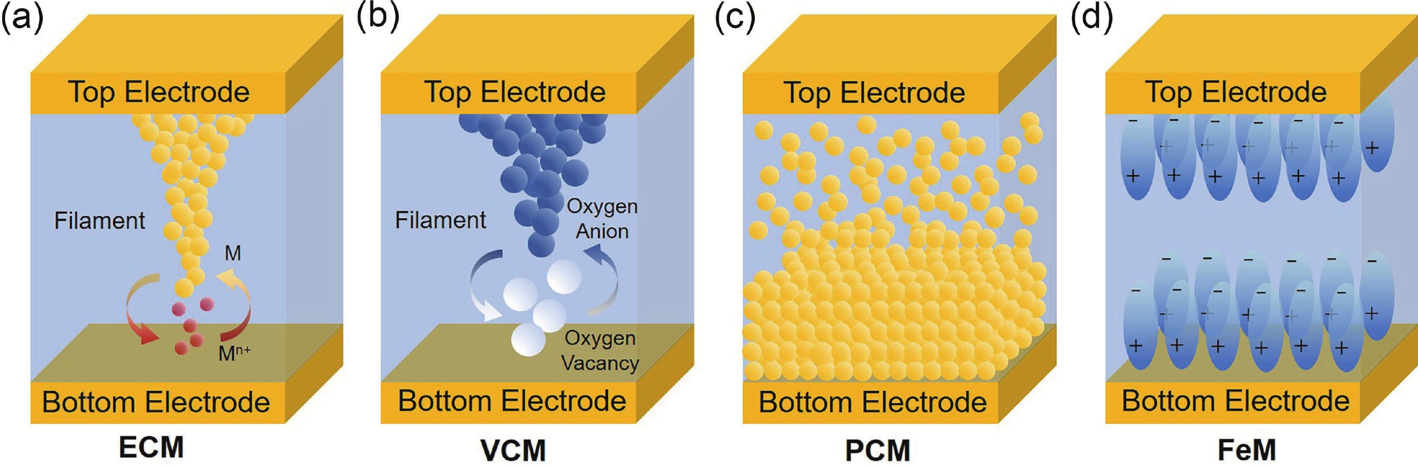
    Fig. 1. (Color online) The working mechanisms of two-terminal memristors. (a) Electrochemical metallization mechanism. (b) Valence change mechanism. (c) Phase change mechanism. (d) Ferroelectric mechanism.
    (Color online) The types of three-terminal synaptic transistors. (a) Floating-gate transistors. (b) Electrolyte-gate transistors. (c) Ferroelectric field-effect transistors. (d) Optoelectronic synaptic transistors.
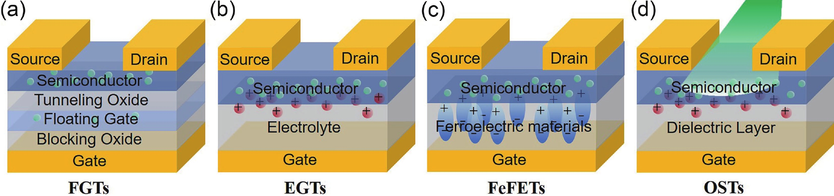
    Fig. 2. (Color online) The types of three-terminal synaptic transistors. (a) Floating-gate transistors. (b) Electrolyte-gate transistors. (c) Ferroelectric field-effect transistors. (d) Optoelectronic synaptic transistors.
    (Color online) (a) Schematic diagram of phototransistor structure. (b) Schematic diagram of the heterojunction band before and after light. (c) Sensor array chip, wires bonding on printed circuit board (scale bar: 5mm). (d) Optical micrograph of 32 × 32 sensor array (scale bar: 500μm). (e) Measured training weight results of a number 8 pattern in the initial state and after training under 405 nm light with a lighting power density of 1 μW/cm2 (pulse width, 250 ms; pulse interval, 250 ms). (f) Measured training weight results of the sensor array after training with 10 pulses under a 405 nm light with various lighting power densities (pulse width, 250 ms; pulse interval, 250 ms). (g) Simulation results of a man’s face in the initial state and after training processes. Reproduced with permission[33]. Copyright 2021, Springer Nature.
    Fig. 3. (Color online) (a) Schematic diagram of phototransistor structure. (b) Schematic diagram of the heterojunction band before and after light. (c) Sensor array chip, wires bonding on printed circuit board (scale bar: 5mm). (d) Optical micrograph of 32 × 32 sensor array (scale bar: 500μm). (e) Measured training weight results of a number 8 pattern in the initial state and after training under 405 nm light with a lighting power density of 1 μW/cm2 (pulse width, 250 ms; pulse interval, 250 ms). (f) Measured training weight results of the sensor array after training with 10 pulses under a 405 nm light with various lighting power densities (pulse width, 250 ms; pulse interval, 250 ms). (g) Simulation results of a man’s face in the initial state and after training processes. Reproduced with permission[33]. Copyright 2021, Springer Nature.
    (Color online) (a) Schematic diagram of bioinspired visual memory unit integrated by image sensor and storage device. (b) Characteristic I–V curve of image sensor, memristor and bioinspired visual memory unit. (c) Imaging and memory behavior of flexible visual memory array. Reproduced with permission[32]. Copyright 2018, Wiley-VCH.
    Fig. 4. (Color online) (a) Schematic diagram of bioinspired visual memory unit integrated by image sensor and storage device. (b) Characteristic I–V curve of image sensor, memristor and bioinspired visual memory unit. (c) Imaging and memory behavior of flexible visual memory array. Reproduced with permission[32]. Copyright 2018, Wiley-VCH.
    (Color online) Comparison of the artificial afferent nervous system and biological afferent nervous system. (a) Biological afferent nerve stimulated by pressure. (b) An artificial afferent nerve made of pressure sensor, organic ring oscillator and synaptic transistor. (c) A photograph of an artificial afferent nerve system. Reproduced with permission[42]. Copyright 2021, American Association for the Advancement of Science.
    Fig. 5. (Color online) Comparison of the artificial afferent nervous system and biological afferent nervous system. (a) Biological afferent nerve stimulated by pressure. (b) An artificial afferent nerve made of pressure sensor, organic ring oscillator and synaptic transistor. (c) A photograph of an artificial afferent nerve system. Reproduced with permission[42]. Copyright 2021, American Association for the Advancement of Science.
    (Color online) (a) Schematic diagram of flexible ferroelectric organic field-effect transistor structure. (b) Schematic diagram of 2 × 2 sensor array of artificial tactile nerve. (c) Infer the order of touch in the 2 × 2 sensor array based on synaptic weight. Reproduced with permission. Copyright 2020[43]. Springer Nature.
    Fig. 6. (Color online) (a) Schematic diagram of flexible ferroelectric organic field-effect transistor structure. (b) Schematic diagram of 2 × 2 sensor array of artificial tactile nerve. (c) Infer the order of touch in the 2 × 2 sensor array based on synaptic weight. Reproduced with permission. Copyright 2020[43]. Springer Nature.
    (Color online) (a) Schematic illustration of the human auditory pathway. (b) Basic structure scheme of the TENG acoustic receptor. (c) A schematic configuration of the acoustic synaptic transistor and the acoustic processing with neuromorphic function. Reproduced with permission[48]. Copyright 2020, Elsevier. (d) Schematics of biological synapse and structure of synaptic transistor. (e) A circuit diagram of an auditory nerve system. Reproduced with permission[49]. Copyright 2019, Elsevier.
    Fig. 7. (Color online) (a) Schematic illustration of the human auditory pathway. (b) Basic structure scheme of the TENG acoustic receptor. (c) A schematic configuration of the acoustic synaptic transistor and the acoustic processing with neuromorphic function. Reproduced with permission[48]. Copyright 2020, Elsevier. (d) Schematics of biological synapse and structure of synaptic transistor. (e) A circuit diagram of an auditory nerve system. Reproduced with permission[49]. Copyright 2019, Elsevier.
    (Color online) (a) Schematic diagram of biological synapse and p–i–n JST. (b) Postsynaptic current of p–i–n JST under negative and positive pulses mimics the different functions of dopamine and acetylcholine in the nervous system: excitement response and memory formation. (c) Schematic diagram of high salt aversion and low salt attraction caused by the synergy of different gustatory receptor neurons. Reproduced with permission[52]. Copyright 2018, Wiley-VCH.
    Fig. 8. (Color online) (a) Schematic diagram of biological synapse and p–i–n JST. (b) Postsynaptic current of p–i–n JST under negative and positive pulses mimics the different functions of dopamine and acetylcholine in the nervous system: excitement response and memory formation. (c) Schematic diagram of high salt aversion and low salt attraction caused by the synergy of different gustatory receptor neurons. Reproduced with permission[52]. Copyright 2018, Wiley-VCH.
    (Color online) (a) Schematic diagram of an artificial olfactory inference system based on an RC system and a classifier for gas classification. (b) Temporal responses of the memristive devices to the spike trains of the response speeds. (c) Temporal responses of the memristive devices to the spike trains of the sensing responses. The complete output is segmented at 0.15 s interval, as presented in the inset of (b). (d) Classification accuracy for testing samples with two types of artificial synapses, that is, ideal and WO3-based ones. (e–g) Classification accuracy for testing samples with reduced (e) spatial, (f) temporal, and (g) spatial and temporal dimensions. Reproduced with permission[54]. Copyright 2021, Wiley-VCH.
    Fig. 9. (Color online) (a) Schematic diagram of an artificial olfactory inference system based on an RC system and a classifier for gas classification. (b) Temporal responses of the memristive devices to the spike trains of the response speeds. (c) Temporal responses of the memristive devices to the spike trains of the sensing responses. The complete output is segmented at 0.15 s interval, as presented in the inset of (b). (d) Classification accuracy for testing samples with two types of artificial synapses, that is, ideal and WO3-based ones. (e–g) Classification accuracy for testing samples with reduced (e) spatial, (f) temporal, and (g) spatial and temporal dimensions. Reproduced with permission[54]. Copyright 2021, Wiley-VCH.
    ChannelElectrolyteElectrode(a)Mechanism(b)ApplicationRef.
    (a) Type of electrodes. Top electrode/bottom electrode for memristors; source/drain/gate for transistors. (b) Mechanism of devices. ECM: electrochemical metallization mechanism; VCM: valence change mechanism; FGT: floating gate transistor; EDLT: electric double layer transistor; ECT: electrochemical transistor; FeFET: ferroelectric field-effect transistor; OST: Optoelectronic Synaptic Transistor.
    P(IID-BT)P(VDF-TrFE)/ P(VP-EDMAEMAES)Au/Au/AlFeFETVisual system[56]
    PEDOT:PSS/PEINafionITO/ITO/PEDOT:PSSEGTVisual system[57]
    PIIDPMMA-MAAAu/Au/AlFGTVisual system[58]
    α-MoO3LiClO4/PEO (Cr/Au)/(Cr/Au)/SiECTVisual system[59]
    WSe2h-BN(Pt/Au)/(Pt/Au)/(Ti/Au)OSTVisual system[60]
    IGZOSAOIZO/IZO/CrECTVisual system[61]
    IGZOHfZrOxAl/Al/TiNFeFETVisual system[62]
    PentaceneCDs/silk/SiO2Au/Au/SiFGTVisual system[63]
    IGZOGO/P(VDF-HFP)/ (EMIM)(TFSI)Au/Au/AuFGTVisual system[64]
    CNTSiO2/Au/SiO2Ti/Pd/PdFGTVisual system[65]
    CH3NH3PbI3Ag/ITOECMVisual system[66]
    PDPP3TChitosanAu/Au/AlEDLTSomatosensory system[67]
    PentaceneP(VDF-TrFE)/ BT NPsAu/Au/NiFeFETSomatosensory system[43]
    Monolayer graphene[EMIM][TFSI]/ PEGDA/HOMPPAu/Au/AuEDLTSomatosensory system[68]
    PDVT-10[LI] [TFSI]Au/Au/SiEDLTAuditory system[48]
    MoS2SiO2(Cr/Au)/ (Cr/Au)/SiECTAuditory system[69]
    PTIIG-NpPS-PMMA-PS /[EMIM][TFSI]Au/Au/SiEDLTAuditory system[49]
    PEO/P3HTPMMA/TiO2Au/Au/SiEDLTGustatory system[52]
    PCDTPTSiO2Au/Au/SiOlfactory system[70]
    WO3W/(PEDOT:PSS/Pt)VCMOlfactory system[54]
    SWCNTc-PVPAg/Ag/AgEDLTOlfactory system[55]
    Table 1. Multifunctional neurosynaptic devices shaping the human perception system.
    Wei Wen, Yunlong Guo, Yunqi Liu. Multifunctional neurosynaptic devices for human perception systems[J]. Journal of Semiconductors, 2022, 43(5): 051201
    Download Citation