• Photonics Research
  • Vol. 10, Issue 7, 1575 (2022)
Kaili Sun1、†, Hui Jiang1、†, Dmitry A. Bykov2, Vien Van3, Uriel Levy4, Yangjian Cai1, and Zhanghua Han1、*
Author Affiliations
  • 1Shandong Provincial Key Laboratory of Optics and Photonic Devices, Center of Light Manipulation and Applications, School of Physics and Electronics, Shandong Normal University, Jinan 250358, China
  • 2Image Processing Systems Institute—Branch of the Federal Scientific Research Centre “Crystallography and Photonics” of Russian Academy of Sciences, Samara 443001, Russia
  • 3Department of Electrical and Computer Engineering, University of Alberta, Edmonton, Alberta T6G 2V4, Canada
  • 4Department of Applied Physics, and Center for Nanoscience and Nanotechnology, The Hebrew University of Jerusalem, Jerusalem, Israel
  • show less
    DOI: 10.1364/PRJ.456260 Cite this Article Set citation alerts
    Kaili Sun, Hui Jiang, Dmitry A. Bykov, Vien Van, Uriel Levy, Yangjian Cai, Zhanghua Han. 1D quasi-bound states in the continuum with large operation bandwidth in the ωk space for nonlinear optical applications[J]. Photonics Research, 2022, 10(7): 1575 Copy Citation Text show less
    Schematic diagram of the structure supporting the 1D QBICs. The inset presents a magnified view of the grating unit cell, which is assumed to extend infinitely along the y direction. The red beams indicate the incident, reflected, and transmitted light.
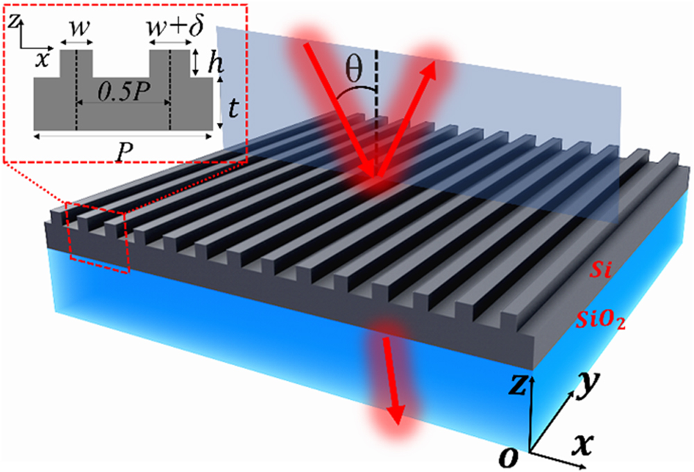
    Fig. 1. Schematic diagram of the structure supporting the 1D QBICs. The inset presents a magnified view of the grating unit cell, which is assumed to extend infinitely along the y direction. The red beams indicate the incident, reflected, and transmitted light.
    (a) Band structure of the BIC/QBIC mode supported by the binary grating waveguide structure when δ is 10 nm. The dotted line represents the light line in the free space. (b) Q factor as a function of incident angle for the QBIC resonances at δ=10 nm. (c) The transmission spectra of a regular grating structure GMR (red line) and binary gratings (black line) both at incident angle of 2°. (d) Dependence of resonance Q factor on the ridge width difference δ, at two incident angles of 3° (diamond) and 5° (circle), respectively.
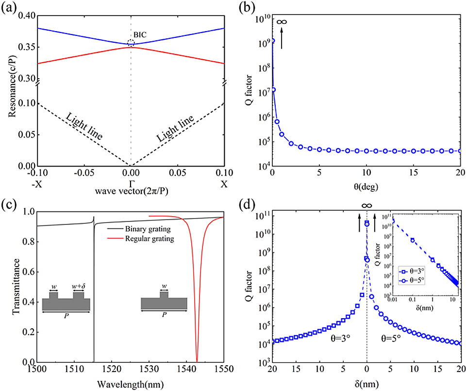
    Fig. 2. (a) Band structure of the BIC/QBIC mode supported by the binary grating waveguide structure when δ is 10 nm. The dotted line represents the light line in the free space. (b) Q factor as a function of incident angle for the QBIC resonances at δ=10  nm. (c) The transmission spectra of a regular grating structure GMR (red line) and binary gratings (black line) both at incident angle of 2°. (d) Dependence of resonance Q factor on the ridge width difference δ, at two incident angles of 3° (diamond) and 5° (circle), respectively.
    (a)–(c) Local transmission spectrum close to the three positions marked in (d), with the inset showing the field distribution of the real part of Ey [the inset of (a) is obtained from eigenfrequency analysis] and the white arrows representing the vectorial distributions of the Poynting vector. The black arrows in each figure indicate incidence, reflection, and transmission, respectively. (d) The relationship between the resonant wavelength of BIC/QBIC modes and the incident angle in the binary grating structure. The three circles of a, b, and c represent the BIC/QBIC modes at different angles.
    Fig. 3. (a)–(c) Local transmission spectrum close to the three positions marked in (d), with the inset showing the field distribution of the real part of Ey [the inset of (a) is obtained from eigenfrequency analysis] and the white arrows representing the vectorial distributions of the Poynting vector. The black arrows in each figure indicate incidence, reflection, and transmission, respectively. (d) The relationship between the resonant wavelength of BIC/QBIC modes and the incident angle in the binary grating structure. The three circles of a, b, and c represent the BIC/QBIC modes at different angles.
    (a) Transmission spectra through the LiNbO3 thin film binary grating structure at three different incident angles of 2°, 3°, and 5°. The geometrical parameters are: P=835 nm, t=350 nm, h=80 nm, w=80 nm, and δ=5 nm. (b) and (c) SFG spectra when one input wavelength is 1490.665 nm at a fixed incident angle of 2° while the other input beam is fixed, respectively, at (b) 3° and (c) 5° while its wavelength is tuned. The red dashed lines correspond to the SFG through the bare LiNbO3 thin film of the same thickness.
    Fig. 4. (a) Transmission spectra through the LiNbO3 thin film binary grating structure at three different incident angles of 2°, 3°, and 5°. The geometrical parameters are: P=835  nm, t=350  nm, h=80  nm, w=80  nm, and δ=5  nm. (b) and (c) SFG spectra when one input wavelength is 1490.665 nm at a fixed incident angle of 2° while the other input beam is fixed, respectively, at (b) 3° and (c) 5° while its wavelength is tuned. The red dashed lines correspond to the SFG through the bare LiNbO3 thin film of the same thickness.
    Kaili Sun, Hui Jiang, Dmitry A. Bykov, Vien Van, Uriel Levy, Yangjian Cai, Zhanghua Han. 1D quasi-bound states in the continuum with large operation bandwidth in the ωk space for nonlinear optical applications[J]. Photonics Research, 2022, 10(7): 1575
    Download Citation