Abstract
1. INTRODUCTION
The concept of bound state in the continuum (BIC) was first proposed in quantum mechanics by von Neumann and Wigner in 1929 [1], predicting the existence of localized eigenstates of the single-particle Schrödinger equation embedded in the continuum of eigenvalue state solutions. This counterintuitive observation is of fundamental importance in quantum mechanics. Over the years, the phenomenon of BIC has also been popularized and extensively studied in various fields, like acoustics [2,3], electronics [4–6], and microwaves [7,8]. In 2008, the concept of BIC was further extended to optical systems for the first time by Marinica
In optics and photonics, researchers have realized both symmetry-protected BICs and accidental BICs, as well as QBIC resonances with finite factors and an easier excitation requirement by introducing some geometrical perturbations in a variety of structures, including gratings [11–13], waveguide arrays [14,15], photonic crystals with near-zero refractive indexes [16,17], integrated photonic circuits [18,19], and metasurfaces [20,21]. A range of amazing properties and applications have been achieved to date with photonic QBICs in applications such as lasing [22], sensing [23] and Raman spectroscopy [24], and the application of QBIC in nonlinear optics [25], twisted light [26], and light–matter interaction [27] is being actively investigated. Unfortunately, most of the reported BICs only occur at very few discrete points in space for a given structure geometry. This is true for both the symmetry-protected and accidental types of BIC. When the ideal BIC is switched to a QBIC resonance, its frequency remains within a narrow spectral band tightly close to that of the original BIC, even at a highly different wavevector away from the BIC point in the space. As a result, the enhanced light–matter interactions can only be achieved within the narrow band for a specific geometry, restricting the applications of BIC in many circumstances where it is required to tune the working frequency or to have multiple inputs beyond the band. As a result, most of the BIC applications in nonlinear optics reported to date are focused on higher harmonic generation [28,29], where only a single light beam at the fundamental frequency is involved. The ultrahigh local electric field enhancement associated with the QBIC resonances significantly improves the nonlinear conversion efficiency [25]. However, there are many circumstances in nonlinear optics where the generation of the target signal frequency requires two or more different input frequencies; e.g., in sum frequency generation (SFG) or difference frequency generation (DFG). To obtain the utmost enhancement based on the BIC effect, all the input frequencies must be at the QBIC resonances. Unfortunately, significant restrictions emerge with a conventional QBIC because, in those applications, the input frequencies may not be within the narrow operation band of QBIC resonance supported by a structure. The situation becomes even worse if there is a need for spectral tunability of the target signal frequency.
In this work, we demonstrate that a binary grating composed of two ridge arrays with the same period and different ridge width on a slab waveguide structure supports a new set of QBIC resonances and can address the above challenges. We note that a similar structure with regular uniform ridge grating supports the ideal BIC at a normal incidence and the QBIC at an inclined incidence, both at a fixed and limited number of frequencies [12]. In contrast, these QBIC resonances supported by the binary grating are distributed continuously along a line over a large spectral range in the space and thus can be considered as 1D QBIC. Using the 1D QBIC supported by a structure with a fixed geometry, it is now possible to arbitrarily choose any frequency within a broad range to achieve enhanced light–matter interactions. This important feature greatly promotes many applications that require multiple input wavelengths, such as SFG or DFG, and is expected to significantly push forward the use of QBIC in applications such as nonlinear optics.
Sign up for Photonics Research TOC. Get the latest issue of Photonics Research delivered right to you!Sign up now
2. STRUCTURE AND RESULTS
A. Dispersion and
Figure 1 shows a schematic sketch of the investigated structure that supports the 1D QBICs. The red dashed box in the inset shows a magnified side view of the unit cell. To demonstrate the working principle, Si (dark grey area, refractive index 3.45) is first assumed in this section as the constituent material for both the slab waveguide and ridges on the substrate of (blue area, refractive index 1.45). To achieve the QBIC effect in the telecom band, we deliberately adjusted the period to 540 nm, and chose as in the standard silicon on insulator (SOI) wafer specification. For the topmost grating layer, we take the width of one ridge as and define another as by introducing the deviation variable , both with a height of 60 nm. For the sake of simplicity and the ease of calculation, it is assumed that all materials are dispersionless. The red arrows in Fig. 1 represent the incident, reflected, and transmitted light beams. Without losing generality, we consider only TE polarization with the electric field parallel to the direction and the incident beam is within the plane onto the structure at an angle of with respect to the axis. Similar results and conclusions can be obtained as well for the TM polarization. A finite-element method based commercial software from COMSOL Multiphysics together with Floquet periodic boundary conditions in the direction and perfectly matched layers (PMLs) in the direction is used for all the calculations.
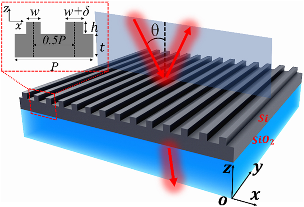
Figure 1.Schematic diagram of the structure supporting the 1D QBICs. The inset presents a magnified view of the grating unit cell, which is assumed to extend infinitely along the
When the ridge width difference is nonzero, the binary grating has a period of to accommodate two ridges within one unit cell and the well-known phenomenon of guided-mode resonance (GMR) [30] is achieved, exhibiting a sharp dip in the transmission spectrum when the following phase-matching condition is satisfied:
Figure 2.(a) Band structure of the BIC/QBIC mode supported by the binary grating waveguide structure when
The fact that the spectral positions of 1D QBIC and the corresponding incident angles are still determined by Eq. (1) suggests that these 1D QBICs can also be considered as GMRs. It is well-known that a regular GMR effect can generate a sharp resonance effect with a large factor [30]. To have a straightforward comparison between the GMR and the 1D QBIC effects supported by a conventional ridge grating and the binary grating, respectively, Fig. 2(c) shows the transmission spectrum at the same incident angle 2° for both the GMR (red line) and the QBIC (black line) with the inset showing the structure schematics for the two cases. Here, is still chosen as 10 nm for the binary grating. It is clearly shown that a much sharper transmission dip is presented for the QBIC resonance than for the GMR. Detailed calculations show that the QBIC resonance has a factor higher than and is two orders of magnitude higher than that of the GMR shown in the same figure.
The above results are obtained with a value of 10 nm. Actually, the general factor of the 1D QBIC resonances over a large bandwidth can be significantly affected by the level of asymmetry between the two ridges. The dependence of resonance factor on at two random incident angles of 3° and 5° is calculated and presented in Fig. 2(d). It is quite evident that the general factor increases with a decrease in the ridge asymmetry. A polynomial fitting of the values as a function of is shown in the inset of Fig. 2(d), and an inversely quadratic dependence of versus is found, in a similar way to the QBIC resonances supported by asymmetric metasurfaces [31]. Actually, the same behavior works for any incident angle. When is nonzero yet small, the 1D QBIC resonances with finite yet ultrahigh factors can be excited. One can choose any wavelength within a broad spectral range to have the QBIC resonance, whose factor can be further controlled by choosing a proper deviation of from 0. These 1D QBIC resonances are of special importance for real applications, thanks to the benefit of the relieved excitation requirement while the local enhancement of electromagnetic fields is weakly affected.
B. Coupled-Mode Theory
The behavior above in Fig. 2 can be actually theoretically explained within the framework of the coupled-mode theory. As we described above, the factor of the QBIC depends on both the incidence angle and ridge width difference . Here, we adopt the spatiotemporal formulation of this theory for the gratings presented in Ref. [32], and write the homogeneous coupled-mode equations as
Here, and define the amplitudes of the two counterpropagating modes of the slab layer; is the group velocity of these modes, and and are the coupling coefficients. Making use of the energy conservation law [33] we can show that is real for lossless structures.
Taking the Fourier transform of Eq. (2), we can arrive at the system of linear equations having nontrivial solutions when
Figure 3.(a)–(c) Local transmission spectrum close to the three positions marked in (d), with the inset showing the field distribution of the real part of
Note that all the parameters used in Eqs. (2) and (3) depend on the ridge width difference . For the considered structure, it is the dependence of on that is the most important. As we demonstrated previously, the eigenmodes of the structure are not excited at . Therefore, the frequency of the symmetric mode is real at , and , where is a real parameter. When is zero, all coefficients in Eq. (3) become real and we obtain the dispersion law for the 1D QBIC: . When the ridge width difference is nonzero, we can solve Eq. (3) with respect to the complex frequency and obtain the factor of the QBIC.
C. Transmission Spectra
We further investigate the properties of the 1D QBIC resonances by studying the transmission spectra of the binary grating at different incidence angles. For the binary grating structure with , in Fig. 3(d) we present the calculated resonance wavelength versus incident angle. When the incident angle increases, the high-frequency branch undergoes a blue shift, while the other branch experiences a red shift to the opposite direction. These trends suggest that the low-frequency branch results from the grating excitation with while the other branch is with in Eq. (1). We choose three points in Fig. 3(d) marked to to demonstrate the formation of BIC/QBIC modes for different cases, where “a” corresponds to the resonances at normal incidence, while “b” and “c” correspond, respectively, to two randomly selected incident angles of 3.5° and 5°. We present both the transmission spectrum and the field distributions, respectively, around these three points in Figs. 3(a)–3(c).
Point “a” has a completely different property compared to other points. Eigenfrequency analysis demonstrates that a resonance with an infinite factor can be found at this point. The transmission spectrum calculations also show that this resonance cannot be excited by a plane wave at normal incidence. In Fig. 3(a), the mode distribution is obtained from the eigenfrequency analysis. These results suggest that point “a” corresponds to the occurrence of an ideal BIC resonance. Although there is a slight level of structural asymmetry between the ridges (), the whole structure is still symmetric if one uses a vertical plane across the center of either ridge. So the resonance at point “a” is an ideal BIC of the symmetry-protected type, and thus cannot be excited by a plane wave at normal incidence. It is seen from the inset of Fig. 3(a) that the electric field is mainly concentrated within the waveguide layer and located between the grating ridge intervals; therefore, it is distributed with perfect antisymmetry. Judging from the same field distributions at higher incident angels [cf. the inset in Figs. 3(a)–3(c)], we believe any other points along the same band away from position “a” can be interpreted as QBIC resonances that result from a perturbation in the incident angle from the symmetry-protected BIC at position “a”. As a result, the QBIC resonance in this high-frequency branch typically has a factor that decreases with an increase in the incident angle. For a larger incident angle, the wavelength of the QBIC has a blue shift. For example, when the incident angle is 3.5°/5°, the QBIC wavelength decreases from the BIC wavelength of 1522.8 nm to 1505.5 nm/1494.9 nm, as marked by points “b” and “c”. Since a larger incident angle means a higher perturbation from normal incidence, the corresponding factor drops slightly, which is consistent with the result in Fig. 2(b). As shown in the insets of Figs. 3(b) and 3(c), the power flow propagates from the left to the right side of one unit cell, along the same direction as the incident beam, which corresponds to the grating diffraction order to be 1.
3. SFG AS AN EXAMPLE OF APPLICATION
To demonstrate that it is possible to randomly select any incident wavelength within a specific range and generate the light in the desired spectral range with a larger freedom of choice by using the 1D QBIC resonances, we choose the process of SFG as a simple example. Here an -cut (the optical axis is along direction) film structure is employed to make use of its relatively high second-order nonlinear susceptibility along the TE polarization. The structure is schematically shown in the inset of Fig. 4(a) and its geometrical parameters are adjusted due to a smaller refractive index (, ) of compared to Si. Figure 4(a) presents the calculated transmission spectra for TE polarization at three different incident angles. It is apparent that a sharp resonance is associated with each incident angle, and the resonance has a blue shift and slightly increasing bandwidth at a larger incident angle. We note that these resonances belong to the short-wavelength branch, as shown in Fig. 3(a).
Figure 4.(a) Transmission spectra through the
The SFG enhancement is most significant when both incident wavelengths match a certain QBIC resonance. We first choose one incident plane wave with a fixed wavelength of at the incident angle of 2°. The second incident beam has an incident angle of 3° while its wavelength is continuously scanned. Both the incident plane waves are assumed to have an electric field amplitude of , corresponding to an intensity of in a vacuum. The SFG is calculated using the FEM method by only considering the value of as [34]. This simplification is valid because is one order of magnitude higher than the other components and is the dominant factor in the second-order nonlinear process. As shown in Fig. 4(b), the SFG is most significant when is tuned as 1478.818 nm, which is exactly the QBIC resonance for the incident angle of 3°, leading to an SFG wavelength of . In the SFG calculations, we assume a grating length of 1 cm is used in the direction to have a valid 2D grating structure, and the power at SFG frequency is calculated by an integral of its Poynting vector only at the lower output port. From the results, it is clear that the SFG efficiency is enhanced by a factor of when both input wavelengths match the QBIC wavelength, compared to the SFG effect through a bare thin film of the same thickness. To have the enhanced SFG at a different target wavelength, keep the wavelength of at 2° and simply tune the incident angle of , which will tune the QBIC resonance to a different wavelength value. For example, when the incident angle of is increased to 5°, the QBIC resonance will switch to 1454.755 nm and the enhanced SFG will then be around 736.246 nm. The SFG results for this case are presented in Fig. 4(c).
One of the requirements to achieve a large efficiency for nonlinear applications with multiple inputs is to have a large modal overlap between the input beams within the nonlinear medium to facilitate the interaction. For the SFG example, we are using the 1D QBIC resonances on the high-frequency branch in Fig. 3(d) for demonstration. As shown by the resonance mode distributions in Figs. 3(a)–3(c), the modes exhibit strong similarities at different incident angles, which indicate that a large modal overlap can be achieved. The significantly enhanced SFG efficiency shown above supports this point. Since resonances on this branch exihibit larger factors at smaller incident angles, it is advantageous to use lower incident angles.
We note that all practical laser sources have certain bandwidths that may be larger than that of the QBIC, and it is only the frequency component of the QBIC resonance whose local electric field will be enhanced. Therefore, a laser source working in the continuous-wave mode with the central wavelength matching the QBIC resonance is preferred as the input for nonlinear applications. It may be challenging to achieve spectral matching. Fortunately, this problem can be circumvented by simply tuning the incident angle, making use of the superior property of continuous distribution with the 1D QBIC effect.
4. DISCUSSIONS AND CONCLUSION
The most significant feature of the 1D QBIC resonances with the binary grating is that the QBICs can be continuously supported following the relation between the resonance wavelength and the incident angle governed by Eq. (1). As a result, one can achieve the QBIC resonance over a large spectrum by tuning the incident angle, and control the overall factor of these 1D QBICs by manipulating the degree of structural asymmetry. The continuous distribution of the QBIC resonances over a broad spectral range is a significant advantage over traditional QBIC resonances, which can only occur around very few discrete positions. As a result, one can manipulate the light–matter interactions at any wavelength within the range, by simply choosing the proper incident angle. As an example, we have demonstrated in Section 3 an enhancement of the SFG process with some spectral tunability by simply changing the incident angle of one input beam.
In summary, we have demonstrated in this work that a binary grating structure composed of two ridge arrays with the same period and slightly different ridge width located on a waveguide slab can be employed to support the 1D QBIC resonances along a continuous curve over a large spectral range in the space. The occurrence of the BIC/QBIC resonances at any wavelength over a broad spectral range for a structure with fixed geometry makes it possible to achieve the enhanced light–matter interactions with more freedoms compared to traditional BICs. We believe that these 1D QBICs can greatly promote many applications requiring multiple input wavelengths, and have great applications in general nonlinear optics. Furthermore, although we use the simple 1D grating structures to demonstrate the formation of the 1D QBIC resonances, the same methodology can be easily extended to more sophisticated 2D composite periodic elements or metasurface structures and to other spectral ranges of the electromagnetic spectrum to have enhanced interactions.
References
[1] J. von Neumann, E. Wigner. Uber merkwiirdige diskrete Eigenwerte. Phys. Z, 30, 465-467(1929).
[2] C. W. Hsu, B. Zhen, A. D. Stone, J. D. Joannopoulos, M. Soljacic. Bound states in the continuum. Nat. Rev. Mater., 1, 16048(2016).
[3] Y. X. Xiao, G. Ma, Z. Q. Zhang, C. T. Chan. Topological subspace-induced bound state in the continuum. Phys. Rev. Lett., 118, 166803(2017).
[4] F. Capasso, C. Sirtori, J. Faist, D. L. Sivco, A. Y. Cho. Observation of an electronic bound state above a potential well. Nature, 358, 565-567(1992).
[5] A. Albo, D. Fekete, G. Bahir. Electronic bound states in the continuum above (Ga,In)(As,N)/(Al,Ga)As quantum wells. Phys. Rev. B, 85, 115307(2012).
[6] C. Álvarez, F. Domínguez-Adame, P. A. Orellana, E. Díaz. Impact of electron-vibron interaction on the bound states in the continuum. Phys. Lett. A, 379, 1062-1066(2015).
[7] T. Lepetit, E. Akmansoy, J. P. Ganne, J. M. Lourtioz. Resonance continuum coupling in high-permittivity dielectric metamaterials. Phys. Rev. B, 82, 195307(2010).
[8] T. Lepetit, B. Kanté. Controlling multipolar radiation with symmetries for electromagnetic bound states in the continuum. Phys. Rev. B, 90, 241103(2014).
[9] D. C. Marinica, A. G. Borisov, S. V. Shabanov. Bound states in the continuum in photonics. Phys. Rev. Lett., 100, 183902(2008).
[10] H. Friedrich, D. Wintgen. Interfering resonances and bound states in the continuum. Phys. Rev. A, 32, 3231-3242(1985).
[11] S. I. Azzam, V. M. Shalaev, A. Boltasseva, A. V. Kildishev. Formation of bound states in the continuum in hybrid plasmonic-photonic systems. Phys. Rev. Lett., 121, 253901(2018).
[12] D. A. Bykov, E. A. Bezus, L. L. Doskolovich. Coupled-wave formalism for bound states in the continuum in guided-mode resonant gratings. Phys. Rev. A, 99, 063805(2019).
[13] K. Sun, Y. Cai, Z. Han. A novel mid-infrared thermal emitter with ultra-narrow bandwidth and large spectral tunability based on the bound state in the continuum. J. Phys. D, 55, 025104(2022).
[14] Y. Plotnik, O. Peleg, F. Dreisow, M. Heinrich, S. Nolte, A. Szameit, M. Segev. Experimental observation of optical bound states in the continuum. Phys. Rev. Lett., 107, 28-31(2011).
[15] E. N. Bulgakov, A. F. Sadreev. Robust bound state in the continuum in a nonlinear microcavity embedded in a photonic crystal waveguide. Opt. Lett., 39, 5212-5215(2014).
[16] M. Minkov, I. A. D. Williamson, M. Xiao, S. Fan. Zero-index bound states in the continuum. Phys. Rev. Lett., 121, 263901(2018).
[17] L. Vertchenko, C. DeVault, R. Malureanu, E. Mazur, A. Lavrinenko. Near-zero index photonic crystals with directive bound states in the continuum. Laser Photon. Rev., 15, 2000559(2021).
[18] C. L. Zou, J. M. Cui, F. W. Sun, X. Xiong, X. B. Zou, Z. F. Han, G. C. Guo. Guiding light through optical bound states in the continuum for ultrahigh-
[19] Z. Yu, X. Xi, J. Ma, H. K. Tsang, C.-L. Zou, X. Sun. Photonic integrated circuits with bound states in the continuum. Optica, 6, 1342-1348(2019).
[20] K. Koshelev, Y. Tang, K. Li, D. Y. Choi, G. Li, Y. Kivshar. Nonlinear metasurfaces governed by bound states in the continuum. ACS Photon., 6, 1639-1644(2019).
[21] A. S. Kupriianov, Y. Xu, A. Sayanskiy, V. Dmitriev, Y. S. Kivshar, V. R. Tuz. Metasurface engineering through bound states in the continuum. Phys. Rev. Appl., 12, 014024(2019).
[22] S. T. Ha, Y. H. Fu, N. K. Emani, Z. Pan, R. M. Bakker, R. Paniagua-Domínguez, A. I. Kuznetsov. Directional lasing in resonant semiconductor nanoantenna arrays. Nat. Nanotechnol., 13, 1042-1047(2018).
[23] Y. Wang, Z. Han, Y. Du, J. Qin. Ultrasensitive terahertz sensing with high-
[24] S. Romano, G. Zito, S. Managò, G. Calafiore, E. Penzo, S. Cabrini, A. C. De Luca, V. Mocella. Surface-enhanced Raman and fluorescence spectroscopy with an all-dielectric metasurface. J. Phys. Chem. C, 122, 19738-19745(2018).
[25] Z. Han, F. Ding, Y. Cai, U. Levy. Significantly enhanced second-harmonic generations with all-dielectric antenna array working in the quasi-bound states in the continuum and excited by linearly polarized plane waves. Nanophotonics, 10, 1189-1196(2021).
[26] E. N. Bulgakov, A. F. Sadreev. Propagating Bloch bound states with orbital angular momentum above the light line in the array of dielectric spheres. J. Opt. Soc. Am. A, 34, 949-952(2017).
[27] K. L. Koshelev, S. K. Sychev, Z. F. Sadrieva, A. A. Bogdanov, I. V. Iorsh. Strong coupling between excitons in transition metal dichalcogenides and optical bound states in the continuum. Phys. Rev. B, 98, 161113(2018).
[28] L. Carletti, K. Koshelev, C. De Angelis, Y. Kivshar. Giant nonlinear response at the nanoscale driven by bound states in the continuum. Phys. Rev. Lett., 121, 33903(2018).
[29] L. Jin, Z. Liu, J. Li, S. Lan, J. Liu, J. Liu, Y. Xu. High-
[30] G. Quaranta, G. Basset, O. J. F. Martin, B. Gallinet. Recent advances in resonant waveguide gratings. Laser Photon. Rev., 12, 1800017(2018).
[31] K. Koshelev, S. Lepeshov, M. Liu, A. Bogdanov, Y. Kivshar. Asymmetric metasurfaces with high-
[32] D. A. Bykov, L. L. Doskolovich. Spatiotemporal coupled-mode theory of guided-mode resonant gratings. Opt. Express, 23, 19234-19241(2015).
[33] S. Fan, W. Suh, J. D. Joannopoulos. Temporal coupled-mode theory for the Fano resonance in optical resonators. J. Opt. Soc. Am. A, 20, 569-572(2003).
[34] L. Kang, H. Bao, D. H. Werner. Efficient second-harmonic generation in high
Set citation alerts for the article
Please enter your email address