
Lu Zhang, Dongxu Zhou, Yiping Lu, Hongzhi Zhang, Guoquan Zhang, "Super-bunched focusing with chirped random-phase gratings," Photonics Res. 8, 503 (2020)
- Photonics Research
- Vol. 8, Issue 4, 503 (2020)
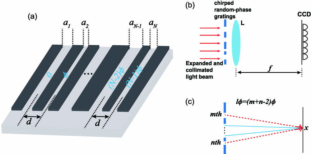
Fig. 1. (a) Schematic diagram of the designed slit-width-chirped random-phase grating. a n n = 1 , 2 , … , N n N ϕ ( t ) [ 0 , 2 π ) d
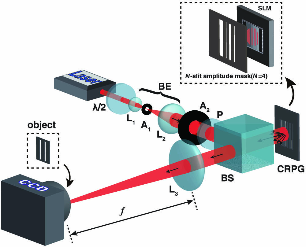
Fig. 2. Schematic diagram of the experimental setup. λ / 2 L 1 L 2 L 3 A 1 A 2 N L 3
Fig. 3. Experimental results for the super-bunched focusing effect with (a) slit-width-chirped random-phase gratings and (b) period-chirped random-phase gratings. The grating period in (a) was fixed at d = 400 μm { a n } B .1. In (b), the slit width was set to be a = 100 μm { b k } B .2. The black solid curves, the blue dash-dotted curves, and the red dotted curves depict the results for N = 4
Fig. 4. Experimental results for the super-bunched focusing effect through chirped random-phase gratings with N = 50 d = 200 μm a = 30 μm B .3 and B.4, respectively.
Fig. 5. Normalized ghost image profiles with super-bunched focusing light fields for (a) the slit-width-chirped random-phase gratings and (b) the period-chirped random-phase gratings. The shaded parts represent the opaque areas of the double-slit mask. The blue dashed curves, the green dotted curves, the red dash-dotted curves, and the pink dash-dot-dotted curves depict the results with N = 4


Set citation alerts for the article
Please enter your email address

© Copyright 2018-2021 | Chinese Laser Press. All Rights Reserved 沪ICP备15018463号-20