Chirped random-phase gratings are designed to produce experimentally a super-bunched focusing effect with a high bunching peak value of and a high visibility of 92.5%, greatly surpassing the theoretical bunching peak of 2 of thermal light. Both slit-width-chirped and period-chirped random-phase gratings are studied theoretically and experimentally. The full width at half-maximum of the super-bunched curve decreases significantly with an increase in the slit number, focusing the photon pairs within a decreasing spot size. This super-bunched focusing effect can be useful for improving the resolution and the visibility of the correlation image simultaneously.
1. INTRODUCTION
Hanbury Brown and Twiss [1,2] recommended the second-order correlation measurement and a new type of interference effect between photon-pair amplitudes, i.e., the bunching effect of thermal light, more than 60 years ago. The physical essence of the bunching effect embodied by the second-order coherence of the light fields is two-photon interference, involving different but indistinguishable alternative ways of triggering a joint-detection event [3,4]. Both classical and quantum theories [3,5–7] were successfully employed to properly interpret the bunching effect of light fields, which was regarded as a milestone in quantum optics.
For thermal light propagating in free space, the normalized second-order spatial correlation function equals 2 when . On the basis of permutation and combination, for an interference experiment with photons detected coincidently by detectors, the peak value of the generalized -photon bunching effect should be [8]. Therefore, naturally a two-photon super-bunched effect is only observed when , in comparison with the bunching peak value of 2 of thermal light. A large bunching peak has been demonstrated to be of essential importance in ghost interference, ghost imaging [9–17], and the multi-photon nonlinear light–matter interaction [18–22]. Several methods were exploited to achieve a super-bunched effect, for instance, through the nonlinear light–matter interaction [23–25], collective two-level atoms coupled with a cavity [26–32], cavity-coupled quantum dot nanolasers [33–35], optical rogue waves and extreme phenomena [36,37], squeezed states [38], and increased intensity fluctuations [39–41]. Note that most of them were in the time domain. Several groups have also paid attention to the super-bunched effect in the spatial domain [42–46]. And was demonstrated initially by our group via multiple two-photon path interference introduced by inserting a pair of mutually first-order incoherent optical channels into a traditional Hanbury Brown–Twiss (HBT) interferometer, surpassing the theoretical limit of 2 for thermal light, which also demonstrates the ability to control the bunching property of thermal light in a linear optical system [42]. Multiple different but indistinguishable two-photon paths could also be introduced through random-phase gratings or wavefront modulation, in which the position-correlated random phase was encoded on the transmitting light fields [46,47]. These indistinguishable two-photon paths of a photon pair triggering a coincidence count also play a key role in the second-order subwavelength interference [48–51].
Chirp is a signal in which the frequency increases (up-chirp) or decreases (down-chirp) with time [52–54], commonly used in sonar, radar, and spread-spectrum communications. In optics, ultrashort laser pulses often exhibit chirp, which interacts with the dispersion properties of the materials in an optical transmission system, increasing or decreasing the total pulse dispersion as the signal propagates [55]. Similarly, for spatial chirping, for example, spatially chirped gratings, it is the grating parameters such as the grating slit width or grating period that vary slowly with position, either linearly or nonlinearly [56]. Spatially chirped gratings have been applied to present focusing properties [56–63] and characteristic diffraction fringes [64,65] in both the near-field and far-field zones, but mainly in the first-order optical coherence range. Nonperiodic gratings were also applied in third-generation synchrotron radiation and high-resolution X-ray spectroscopy [66,67].
Sign up for Photonics Research TOC. Get the latest issue of Photonics Research delivered right to you!Sign up now
In this paper, we are mainly concerned with the two-photon bunching properties of chirped random-phase gratings (CRPGs). Two types of CRPGs are considered. One is where the grating period is fixed but the slit width is chirped. The other is where the slit width is fixed but the grating period is chirped. With CRPGs, superposition of multiple different but indistinguishable two-photon paths is introduced, and the normalized second-order spatial correlation function shows a bunching curve with a much higher peak and a much narrower profile than those of thermal light, achieving a two-photon super-bunched focusing effect, which is potentially useful for applications such as correlation imaging, microfabrication, and enhancement of high-order nonlinear light–matter interaction.
2. THEORY
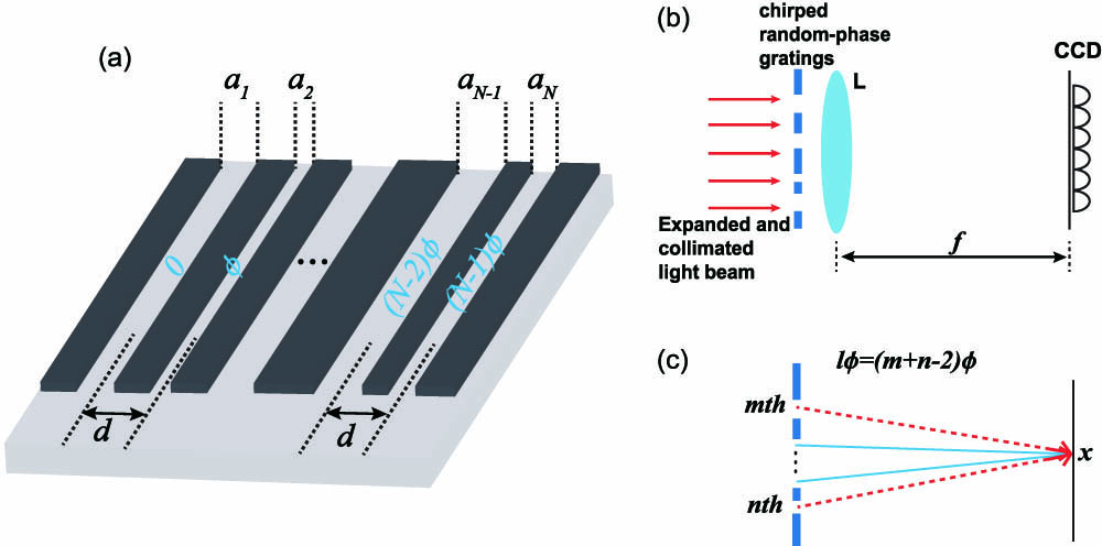
Figure 1.(a) Schematic diagram of the designed slit-width-chirped random-phase grating. () is the width of the th slit, and is the total slit number of the grating; is a random phase changing with time among , and is the fixed period of the grating. (b) Schematic configuration for studying the coherence property of the light field transmitting through the chirped random-phase grating in the Fraunhofer zone, where L represents a lens for collecting the scattering light from the chirped random-phase gratings and CCD is the charge-coupled device camera for recording the intensity distribution on the focal plane of lens L. (c) Schematic diagram of indistinguishable two-photon paths.
Let us consider the first- and second-order interference effects of the light field transmitting through a slit-width-chirped random-phase grating in the Fraunhofer zone when a collimated single-mode laser beam is incident normally onto the slit-width-chirped random-phase grating. The schematic configuration for studying the first- and second-order coherence of the light field transmitting through CRPGs is illustrated in Fig. 1(b), where L is a lens to collect the scattering light from the CRPG and CCD is a charge-coupled device camera for recording the intensity distribution on the focal plane of lens L. In the one-dimensional case and under the paraxial approximation, the field operator on the detection plane can be expressed as where is the annihilation operator of the light field and , , and are the wavelength of the light source, the transverse coordinate on the detection plane, and the focal length of lens L, respectively. One sees that multiple diffraction orders of the grating are taken into account. For simplicity, here we restrict ourselves to the case where the grating parameters are not in the subwavelength range and the paraxial approximation is always satisfied, and we just consider the spatial coherence properties of the light fields. The synchronous first-order spatial correlation function can be calculated as where is the eigenvalue of the field operator on the state of the source and represents the ensemble average. It is evident that the intensity distribution on the detection plane is the sum of the diffraction intensities from slits of the slit-width-chirped random-phase grating, and no stationary first-order interference pattern can be observed due to the condition . However, the case will be totally different when the two-photon interference is considered, as we will show below.
The synchronous second-order spatial correlation function on the detection plane can be expressed as
By substituting Eq. (1) into Eq. (3) and taking into consideration the condition if , one can obtain where () or 1 () and and represent the th and the th slits of the grating, respectively. There is only one valid two-photon path if the two photons triggering the coincidence counting come from the same slit. Note that there are many twin two-photon paths originating from different pairs of slits , , , and so on, whose amplitudes contain the same random phase , as shown in Fig. 1(c). These two-photon paths are indistinguishable in principle. Our previous work has proved that the amplitude superposition of all these different but indistinguishable two-photon paths with the same random phase can enhance the two-photon interference with a signature of high visibility in a random-phase grating [47].
The normalized second-order spatial correlation function can then be calculated as where
One sees that the second-order spatial correlation function on the detection plane is a weighted superposition of a set of periodic interference fringes, in which the weight function is the product of multiple sinc functions characterizing the two-photon paths, with the two photons originating from two slits separated by and having the same random phase . These periodic interference fringes have different interfering periods , and they are exactly in phase only when , while they become gradually out of phase with the increase of , leading to a two-photon bunching peak at . In general, the bunching profile could be very complicated, depending on the structure parameters of the CRPGs. However, super-bunched focusing with a bunching peak much higher and a bunching profile much narrower than those of thermal light can be achieved by optimizing the structure parameters of the CRPGs. In the following, we will give an optimization procedure to produce the super-bunched focusing effect through the CRPGs.
For simplicity, we fix the position of one detector at and scan the other detector at on the detection plane, which is also in accordance with the following experiments in Section 3. In this case, the normalized second-order spatial correlation function can be simplified as and its bunching peak can be calculated as where is the total slit number of the CRPGs. It is seen that the bunching peak increases with an increasing grating slit number , and is larger than 2, the bunching peak of thermal light, when .
Since the super-bunched focusing effect is defined in comparison to the bunching curve of thermal light in the traditional HBT interferometer, we therefore assume the super-bunched profile of the CRPGs in the formula , in which the parameter characterizes the spot size of the super-bunched profile of the CRPGs. The larger the parameter , the smaller the spot size of the super-bunched profile. The super-bunched focusing effect is achieved when the spot size of the super-bunched profile of the CRPG is smaller than that of the bunching curve of thermal light in the traditional HBT interferometer. The visibility of the super-bunched curve is
Obviously, the visibility, increasing with an increasing , can surpass 50% and asymptotically approach 100%.
To achieve a super-bunched focusing profile in the formula , we optimize the grating slit width of the CRPGs by means of a MATLAB-implemented nonnegative least squares algorithm [68]. In this case, the sum of the squared residual error and the total sum of squares can be expressed respectively as where is the mean value of the fitting function . It is the optimal solution when the coefficient of determination gets closest to 1. But in practice, it is considered to be an effective fitting when . A set of equations (see Appendix A) can be obtained with the slit width of the CRPGs as the variable, which can be solved to get the optimal silt width set for the super-bunched focusing effect. Several examples with different total slit numbers , 8, 16, and 50 are given in Appendices B.1 and B.3. Note that here the chirping is usually nonlinear in order to suppress the sidelobes beyond the focusing point.
We have theoretically shown that if the grating period is fixed while the slit width is chirped, the super-bunched focusing effect can be obtained. In the other case—for a period-chirped random-phase grating, where the slit width is fixed but the period is chirped—one can also demonstrate the super-bunched focusing effect. By employing a similar procedure to the case with slit-width-chirped random-phase gratings, one obtains the normalized second-order spatial correlation function where and are the fixed slit width and the th grid line of the gratings, respectively, satisfying , with being the chirped grating period at the th slit. In Eq. (12), we replace the grating period with the grating grid line in order to simplify the calculation. The same optimization procedure can be employed to get an optimized set for the super-bunched focusing effect. Several examples with different total slit numbers , 8, 16, and 50 are also given in Appendices B.2 and B.4.
One sees that theoretically the super-bunched focusing effect is mainly determined by the grating slit number and the grating period . When the grating slit number is fixed, the focusing spot size is mainly determined by the grating period . A larger grating period results in a smaller focusing spot size. In the slit-width-chirped random-phase grating case, the grating period is uniform and fixed. However, in the case with the period-chirped random-phase grating, the grating period is chirped, which will induce a broadening effect on the focusing spot size. Therefore, with the same grating slit number , the focusing spot size with the slit-width-chirped random-phase grating is always smaller than that with the period-chirped random-phase grating. On the other hand, the field will have a tighter focusing spot size with a larger grating slit number . In practice, however, with a larger grating slit number , the optimization procedure for getting the optimal grating parameters will require much longer computation time, and the grating fabrication process should also be precise enough, because any fabrication deviation from the optimal grating parameters will result in a broadening effect on the focused spot size. Therefore, there is a trade-off between the cost and the performance in choosing an appropriate , and it is better to choose an appropriate according to the requirement on the focused spot size in practical applications. In addition, one sees that theoretically the bunching peak value is the same for both CRPGs, and it asymptotically approaches , which could be very high with increasing . In practice, however, the grating slit number is always limited because of the limited grating size. Moreover, the bunching peak value is also affected by the optimization process and the fabrication process of the CRPG. To get a high bunching peak value, one has to suppress the sidelobes of the bunching curve. The lower the sidelobes, the higher the bunching peak value.
In the following, we will demonstrate experimentally this super-bunched focusing effect through the proposed CRPGs.
3. EXPERIMENTAL DEMONSTRATION AND DISCUSSION
Figure 2.Schematic diagram of the experimental setup. , half-wave plate; , , , lenses; , , irises; BE, beam expander; P, polarizer; BS, 50∶50 beam splitter; CRPG, chirped random-phase grating; CCD, charge-coupled device camera. The straight arrows in the optical path indicate the propagating and scattering light. The upper-right inset shows the detailed structure of the chirped random-phase grating, which is composed of an -slit black–white transmitting amplitude mask and an SLM, and they are placed as close as possible. The lower-left inset shows the object placed on the focal plane of in the ghost imaging experiments.
Figure 3.Experimental results for the super-bunched focusing effect with (a) slit-width-chirped random-phase gratings and (b) period-chirped random-phase gratings. The grating period in (a) was fixed at μ, and the chirped slit width values are listed in Appendix B.1. In (b), the slit width was set to be μ, and the chirped grating grid lines are listed in Appendix B.2. The black solid curves, the blue dash-dotted curves, and the red dotted curves depict the results for , 8, and 16, respectively.
Figure 4.Experimental results for the super-bunched focusing effect through chirped random-phase gratings with . (a) Slit-width-chirped random-phase grating with a fixed period μ, (b) period-chirped random-phase grating with a fixed slit width μ. The corresponding structure parameters can be found in Appendices B.3 and B.4, respectively.
Figure 5.Normalized ghost image profiles with super-bunched focusing light fields for (a) the slit-width-chirped random-phase gratings and (b) the period-chirped random-phase gratings. The shaded parts represent the opaque areas of the double-slit mask. The blue dashed curves, the green dotted curves, the red dash-dotted curves, and the pink dash-dot-dotted curves depict the results with , 8, 16, and 50, respectively. For comparison, the black solid curves show the case of a pseudo-thermal light field generated through a phase-only SLM.
In conclusion, we have designed two types of CRPGs, the slit-width-chirped and the grating-period-chirped random-phase gratings, through which the two-photon super-bunched focusing effect can be realized in the Fraunhofer zone. Theoretically, the bunching peak and the visibility of the super-bunched curves can asymptotically reach and 100%, respectively, where is the total slit number of the CRPGs. Experimentally, we verified that the bunching peak and the visibility of the two-photon bunching curves for the light transmitting through the CRPGs increased with an increasing , and a bunching peak of and a visibility of 92.5% were demonstrated through a period-chirped random-phase grating with a fixed slit width of 30 μm and . The FWHM of the super-bunched curve was confirmed to decrease with an increasing , and a photon-pair bunched spot size with an FWHM of 70 μm was achieved through a slit-width-chirped random-phase grating with a fixed grating period of 200 μm and , therefore focusing the photon pairs with greatly improved spatial resolution. This super-bunched focusing effect could have important potential applications such as correlation imaging with improved visibility and spatial resolution or enhanced nonlinear light–matter interaction.
APPENDIX A: EQUATION SET USED TO OPTIMIZE THE GRATING STRUCTURE PARAMETERS OF THE CHIRPED RANDOM-PHASE GRATINGS
For the case with the slit-width-chirped random-phase gratings, the equation set used to optimize the slit width of the CRPGs is as follows:
For the case with the period-chirped random-phase gratings, a similar equation set is used, but with the variables replaced by the grating grid line width .
APPENDIX B: OPTIMIZED STRUCTURE PARAMETERS OF THE CHIRPED RANDOM-PHASE GRATINGS