• Journal of Semiconductors
  • Vol. 43, Issue 6, 062303 (2022)
Xuyang Wang1、2、3, He Jia3, Junhui Li3, Yumei Guo3, and Yu Liu1
Author Affiliations
  • 1State Key Laboratory on Integrated Optoelectronics, Institution of Semiconductors, Chinese Academy of Sciences, Beijing 100083, China
  • 2University of Chinese Academy of Sciences, Beijing 100049, China
  • 3Beijing Shiweitong Science & Technology Co., Ltd. , Beijing 100176, China
  • show less
    DOI: 10.1088/1674-4926/43/6/062303 Cite this Article
    Xuyang Wang, He Jia, Junhui Li, Yumei Guo, Yu Liu. Optical transmitter module with hybrid integration of DFB laser diode and proton-exchanged LiNbO3 modulator chip[J]. Journal of Semiconductors, 2022, 43(6): 062303 Copy Citation Text show less
    (Color online) Diagrammatic sketch of the module.
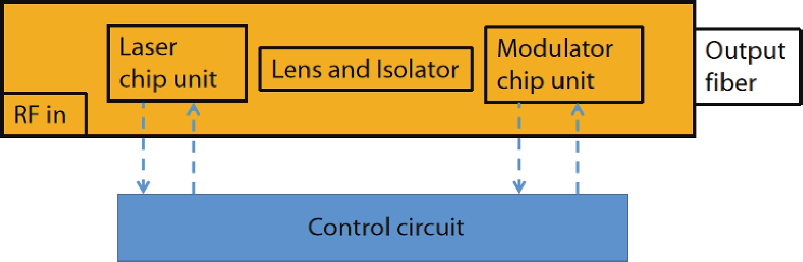
    Fig. 1. (Color online) Diagrammatic sketch of the module.
    (Color online) Diagrammatic sketch of the laser chip unit.
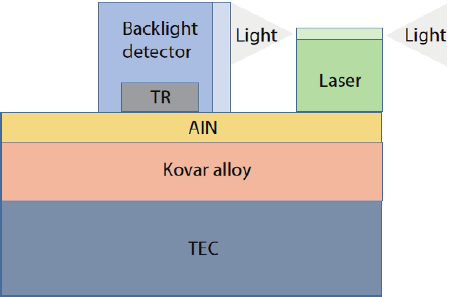
    Fig. 2. (Color online) Diagrammatic sketch of the laser chip unit.
    (Color online) Sketch of the modulator chip unit.
    Fig. 3. (Color online) Sketch of the modulator chip unit.
    (Color online) Optical path of the module.
    Fig. 4. (Color online) Optical path of the module.
    (Color online) Simulation results of normalized optical output efficiency of the module vs. (a) rotated angle of the fiber, (b) optical axis offset distance of the lens, (c) optical axis offset distance of the fiber to the cocenter optical axis, and (d) the MFD of the modulator waveguide.
    Fig. 5. (Color online) Simulation results of normalized optical output efficiency of the module vs. (a) rotated angle of the fiber, (b) optical axis offset distance of the lens, (c) optical axis offset distance of the fiber to the cocenter optical axis, and (d) the MFD of the modulator waveguide.
    (Color online) (a) MZ-modulator waveguide structure. (b) Simulation results of extinction ratio (on/off) and split ratio variation vs. normalization angle. (c) Simulation results of extinction ratio (on/off) and coupling ratio vs. two arms distance.
    Fig. 6. (Color online) (a) MZ-modulator waveguide structure. (b) Simulation results of extinction ratio (on/off) and split ratio variation vs. normalization angle. (c) Simulation results of extinction ratio (on/off) and coupling ratio vs. two arms distance.
    Simulation results of the electro-optic response of the module.
    Fig. 7. Simulation results of the electro-optic response of the module.
    (Color online) Hybrid integrated optical transmitter module.
    Fig. 8. (Color online) Hybrid integrated optical transmitter module.
    P–I curve of the DFB laser chip.
    Fig. 9. PI curve of the DFB laser chip.
    (a) EO bandwidth and (b) ER test results of the LiNbO3 modulator chip.
    Fig. 10. (a) EO bandwidth and (b) ER test results of the LiNbO3 modulator chip.
    (a) EO bandwidth and (b) ER test results of the module.
    Fig. 11. (a) EO bandwidth and (b) ER test results of the module.
    (Color online) Output RF power of a linear tone and of a third-order intermodulation vs. the RF input power.
    Fig. 12. (Color online) Output RF power of a linear tone and of a third-order intermodulation vs. the RF input power.
    Laser’s drive current (mA)Laser’s power (mW)Module’s power (mW)Optical output efficiency (%)
    50.8016.603.4520.78
    101.0031.106.6021.22
    200.0056.3012.1521.58
    227.0063.1013.7021.71
    Table 1. Test results of the optical output efficiency.
    Xuyang Wang, He Jia, Junhui Li, Yumei Guo, Yu Liu. Optical transmitter module with hybrid integration of DFB laser diode and proton-exchanged LiNbO3 modulator chip[J]. Journal of Semiconductors, 2022, 43(6): 062303
    Download Citation