
Jue Wang, Chengkun Cai, Feng Cui, Min Yang, Yize Liang, Jian Wang. Tailoring light on three-dimensional photonic chips: a platform for versatile OAM mode optical interconnects[J]. Advanced Photonics, 2023, 5(3): 036004
- Advanced Photonics
- Vol. 5, Issue 3, 036004 (2023)
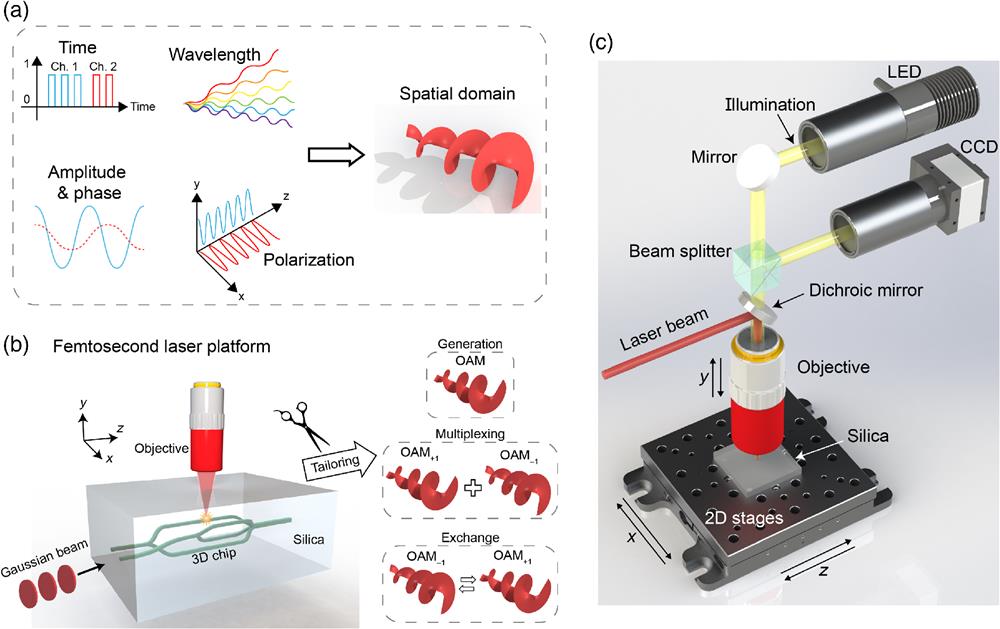
Fig. 1. (a) Multiple physical dimensions of light waves: from traditional ones to the spatial domain (e.g., OAM modes). (b) Concept of 3D photonic chips fabricated by FSLW for tailoring spatial modes (OAM generation/multiplexing/exchange). (c) Fabrication setup for FSLW.
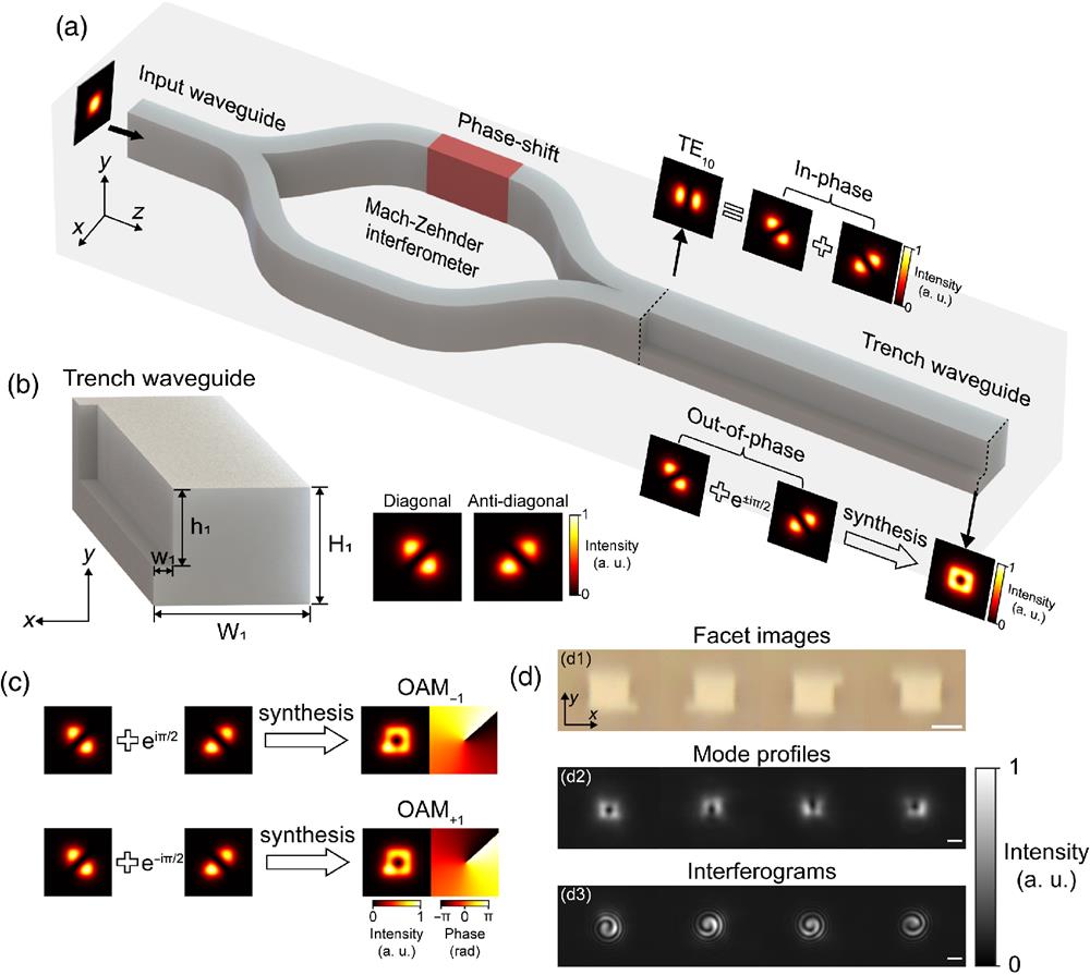
Fig. 2. On-chip OAM mode generator. (a) Concept and principle of the trench-based OAM generator. (b) Structure of trench waveguide and its supporting higher-order modes. (c) Simulated LP-like modes and their synthesized OAM modes. (d) Experimental results of OAM generator with different trench locations: (d1) trench facet images captured by an optical microscope, (d2) measured mode profiles, and (d3) measured interferograms (interference with a reference Gaussian beam). Scale bar,
Fig. 3. On-chip OAM mode multiplexer. (a) Concept and principle of the trench-based OAM mode multiplexer. (b) Structure of the trench waveguide and the supported higher-order eigenmodes (
Fig. 4. (a) Middle, photo of the packaged on-chip OAM mode multiplexer and demultiplexer. Left, zoom-in view of the OAM mode multiplexer. Right, zoom-in view of the OAM mode demultiplexer. (b) Experimental setup for chip–chip optical interconnects with OAM modes. PC, polarization controller; EDFA, erbium-doped fiber amplifier; AWG, arbitrary waveform generator; OC, optical coupler; SMF, single-mode fiber; and VOA, variable optical attenuator. (c) Measured crosstalk matrix. (d) Measured BER performance and constellations.
Fig. 5. (a) Photos of the packaged on-chip OAM mode multiplexer (left), OAM mode demultiplexer (middle), and unpackaged OAM mode (de)multiplexers (right) in the silica substrate. (b) Experimental setup for chip–fiber–chip optical interconnects with OAM modes. (c) Measured intensity profiles of OAM modes after propagating through the 2-km OAM fiber. (d) Measured crosstalk matrix. (e) Measured BER performance and constellations.

Set citation alerts for the article
Please enter your email address
© Copyright 2018-2021 | Chinese Laser Press. All Rights Reserved 沪ICP备15018463号-20