• Journal of Semiconductors
  • Vol. 41, Issue 10, 102802 (2020)
R. Singh1, T. R. Lenka1, R. T. Velpula2, B. Jain2, H. Q. T. Bui2, and H. P. T. Nguyen2
Author Affiliations
  • 1Department of Electronics & Communication Engineering, National Institute of Technology Silchar, AS, 788010, India
  • 2Department of Electrical and Computer Engineering, New Jersey Institute of Technology, Newark, NJ, 07102, USA
  • show less
    DOI: 10.1088/1674-4926/41/10/102802 Cite this Article
    R. Singh, T. R. Lenka, R. T. Velpula, B. Jain, H. Q. T. Bui, H. P. T. Nguyen. Investigation of current collapse and recovery time due to deep level defect traps in β-Ga2O3 HEMT[J]. Journal of Semiconductors, 2020, 41(10): 102802 Copy Citation Text show less

    Abstract

    In this paper, drain current transient characteristics of β-Ga2O3 high electron mobility transistor (HEMT) are studied to access current collapse and recovery time due to dynamic population and de-population of deep level traps and interface traps. An approximately 10 min, and 1 h of recovery time to steady-state drain current value is measured under 1 ms of stress on the gate and drain electrodes due to iron (Fe)–doped β-Ga2O3 substrate and germanium (Ge)–doped β-Ga2O3 epitaxial layer respectively. On-state current lag is more severe due to widely reported defect trap EC – 0.82 eV over EC – 0.78 eV, -0.75 eV present in Iron (Fe)-doped β-Ga2O3 bulk crystals. A negligible amount of current degradation is observed in the latter case due to the trap level at EC – 0.98 eV. It is found that occupancy of ionized trap density varied mostly under the gate and gate–source area. This investigation of reversible current collapse phenomenon and assessment of recovery time in β-Ga2O3 HEMT is carried out through 2D device simulations using appropriate velocity and charge transport models. This work can further help in the proper characterization of β-Ga2O3 devices to understand temporary and permanent device degradation.

    1. Introduction

    There has recently been considerable interest in monoclinic β-phase of gallium oxide (β-Ga2O3) inspired by its excellent material characteristics—large energy bandgap EG ~ 4.9 eV[1], high breakdown electric field EBr up to 8 MV/cm[2], and high electron velocity vsat ~ 1.5 × 107 cm/s[3]. Wide variety of intentional n-type dopants—Si, Ge, and Sn as shallow donors facilitate to achieve electron concentrations ~ 1 × 1020 cm–3[4], although p-type doping in Ga2O3 shows inconsistent findings[5, 6]. Additionally, with the help of low-cost melt growth techniques, such as Czochralski[7], and floating zone[8], large size Ga2O3 bulk substrate can be grown and thus offers cost competitiveness over other wideband semiconductors—GaN and SiC. The availability of low cost and large size β-Ga2O3 bulk crystalline substrates further enables different epitaxial technologies, such as molecular beam epitaxy (MBE), and halide vapor phase epitaxy (HVPE) to grow Ga2O3 with low crystal defects on native substrate. To compensate unintentional Silicon (Si) incorporation during growth of Ga2O3, deep level acceptors such as Mg, and Fe are used to achieve semi insulating bulk crystals[2], and controls substrate leakage. Out of the promising n-type dopants, Si, Ge, and Sn; Ge shows preferred choice for β-Ga2O3 devices[4].

    Several experimental studies on defects throughout the entire bandgap of β-Ga2O3 (010) layers have used deep level transient spectroscopy (DLTS) and deep level optical spectroscopy (DLOS) techniques[912]. Three distinct trap states at wC – 0.1 eV, 0.2 eV, and 0.98 eV in Ge-doped (010) β-Ga2O3 grown using plasma assisted MBE[9], EC – 0.62 eV, 0.82 eV, 1 eV in unintentionally doped (UID) (010) β-Ga2O3 using edge-defined film-fed growth (EFG)[10], EC – 0.55 eV, 0.74 eV, and 1.04 eV[11] in β-Ga2O3 crystal grown using Czochralski method, and two deep level traps at EC – 0.78 eV (due to Fe impurities) and EC – 0.75 eV (due to intrinsic defect)[12] in upper part of the bandgap with concentrations varying from 1014 to 1016 cm−3 have been demonstrated.

    With the distinct trap level defects reported so far, device performance can be easily questioned unless different trap sources and their individual effects on specific output parameters are fully established because device degradation may be reversible or permanent in nature. Significant progress in Ga2O3 based electronic devices such as Schottky diodes[13], metal semiconductor FET (MESFET)[2], metal oxide semiconductor FET (MOSFET)[14, 15], modulation doped FET (MODFET)[16], and HEMT[17] have been reported with good DC and RF performance, mainly due to Ga2O3 excellent material properties. Traps in the device can affect thermal characteristics, including on resistance (Ron) and threshold voltage (VTh), a shift of 0.78 V in VTh was measured due to two distinct trap levels at 0.7 eV, and 0.77 eV in β-Ga2O3 MESFETs on Fe-doped β-Ga2O3 substrate[18]. Dynamic dispersion in drain characteristics led current lag due to trap at EC − 0.75 eV was demonstrated in back-gated Ga2O3 based MOSFET[19].

    Potential application of β-Ga2O3 based devices beg the question of whether the device degradation due to various traps EC – 0.98, 0.82, 0.78, 0.75 eV[9, 10, 12] is temporary or permanent in nature? In this work, we focus on traps originated from Fe-doped β-Ga2O3 substrate, and Ge-doped epitaxial layer on Sn-doped β-Ga2O3 substrate to model the reversible current collapse phenomenon along with measurement of current recovery time to its steady state value.

    2. Device structure and simulation framework

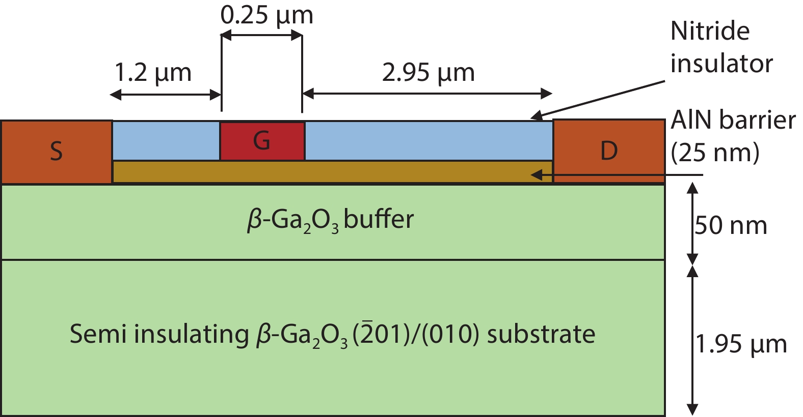
    Fig. 1 shows device structure of AlN/β-Ga2O3 HEMT which is analysed in this report. The sequence of materials comprise of 25 nm AlN barrier layer on 2 μm β-Ga2O3 substrate. Gate material of Au/Ni with gate length, LG of 0.25 μm and Schottky barrier height of 0.8 eV is set by fixing the work function, ϕM of the gate metal of 2.2 eV, electron affinity of the AlN barrier is set as 1.4 eV[20] in material properties. Source/drain electrodes are considered to be perfectly Ohmic. The gate–source (LGS), gate–drain (LGD), and source–drain (LSD) spacing are 1.2, 2.95, and 4.4 μm, respectively. Silicon nitride (Si3N4) insulator of 25 nm is used as surface passivation to suppress current collapse as per experimental device[2].

    (Color online) Schematic cross sectional view of the analysed device structure.

    Figure 1.(Color online) Schematic cross sectional view of the analysed device structure.

    Using electron and hole effective masses of β-Ga2O3[21], total conduction band (NC) and valence band (NV) density of states of 3.6 × 10¹⁸ and 2.86 × 1020 cm−3, respectively, were calculated, and other parameters were considered from Ref. [17].

    For undoped AlN layer default material parameters as mentioned in Ref. [22] are considered except electron affinity (χ = 1.4 eV). Due to low in-plane lattice mismatch between AlN/β-Ga2O3 heterojunction, spontaneous and piezoelectric polarization built in model[22] is activated for AlN material region. A large conduction band offset (CBO), ΔEC = 1.75 eV[20] offers polarization induced sheet charge density σ = 5.617 × 10¹³ C/cm2[23] at the heterointerface due to sole polarization of AlN layer. In absence of p-type carriers, β-Ga2O3 based devices are unipolar, so negative differential mobility model as given by Eq. (1) is chosen for β-Ga2O3 material region and default values of parameters[22] are replaced by mobility model[3]. The low-field electron mobility of 140 cm2/(V·s) as reported in Ref. [3] is in good agreement with Hall measurements electron mobility of 162 cm2/(V·s)[17].

    ${\mu _{\rm{n}}}\left( E \right) = {\rm{}}\dfrac{{{\mu _{{\rm{n}}0}} + {\rm{}}\dfrac{{v_{\rm{sa}{{\rm{t}}_{\rm{n}}}}}}{E}{\rm{}}{{\left( {\dfrac{E}{{{\rm{ECRITN}}}}} \right)}^{{\rm{gamman}}}}}}{{1 + {\rm{}}{{\left( {\dfrac{E}{{{\rm{ECRITN}}}}} \right)}^{{\rm{gamman}}}}}}.$ ()

    Based on previous published reports[912], among the four electron trap levels—E1, E2, E3, and E4; the most prominent is E2 and especially dominant in ( 01) sample, and the source of this trap level is intentional dopant Fe[12]. So to quantify the effect of Fe dopants led current collapse of drain current, the β-Ga2O3 substrate is doped with iron (Fe) as acceptor traps with energy level EC –0.78 eV, and 0.75 eV[12]. The Fe doping in the substrate has a Gaussian profile with peak concentration of 1018 cm–3 at y = 1.0 μm, and gradually drops to 1016 cm–3 near the surface. In order to analyse the effect of traps, generated by commonly used n-type dopants, Ge in β-Ga2O3 epitaxial layer, three trap levels at EC −0.1 eV, −0.2 eV, −0.98 eV are uniformly doped in 50 nm buffer layer. In this case, the substrate is doped with n-type dopant (Sn) concentration of 1018 cm–3 to minimize the Fe effect in epitaxial layer as demonstrated in Ref. [9]. The state EC –0.98 eV is also confirmed by Zhang etal.[10] as EC –1.0 eV by DLTS in Ni/β-Ga2O3 Schottky diode on unintentional doped (UID) (010) substrate by edge-defined film-fed growth (EFG). All the trap levels are analysed in regard of current collapse phenomenon and are summarized in Table 1 with other characteristics. Only deep level traps with concentration ≥ 1015 cm–3 are considered.

    Table Infomation Is Not Enable

    3. Results and discussions

    The proposed device is analysed under three different conditions—gate stress, drain stress, and gate–drain stress. In all three bias conditions, device is biased in low stress and high stress state for 0.1 to 1 ms with respective DC bias at the gate and drain terminals. During initial bias condition, the device is simulated for output drain current under DC bias at gate and drain terminal. After applying a DC bias of VGS = 0 V and VDS = 5 V, this initial bias condition is maintained for 1 ms in dynamic mode. Then, the device is pulsed into high stress state, −25 V on the gate (in gate stress condition); 25 V on the drain terminal (in drain stress); and −25 to 25 V on the gate and drain terminals respectively for another 1 ms, as shown in Fig. 2. Then, the device is returned to its original bias condition. Since we are analysing the recoverable current collapse phenomenon which is not permanent in nature[24], in post-stress condition traps should gradually return to steady state occupancy state. To quantify the recovery time to steady state, bias condition is analysed for a longer time in the order of 105 s in post stress condition. Fig. 3 shows current collapse phenomenon resulting of stress bias, as shown in Fig. 2. The drain current spikes momentarily to its maximum value corresponding to VGS = 0 V and VDS = 25 V and collapses at 2 ms. The trapping of electrons in deep level defects causes this undesirable effect and degrades the device performance.

    (Color online) Pre-stress and post-stress bias voltages at gate and drain terminals.

    Figure 2.(Color online) Pre-stress and post-stress bias voltages at gate and drain terminals.

    (Color online) Pre-stress and post-stress drain current. Inset: current collapse.

    Figure 3.(Color online) Pre-stress and post-stress drain current. Inset: current collapse.

    To analyse the effect of these deep level traps under gate-stress condition, the drain bias remains at fixed bias of 5 V; the device is driven into pinch-off (high stress at gate –25 V for 1 ms) followed by steady state bias. The resulting drain current collapse and recovery time is shown in Fig. 4. It is evident that current degrades momentarily and almost full current recovery happens at time t = 2 ms.

    (Color online) Trapping and de-trapping of defect trap under gate stress.

    Figure 4.(Color online) Trapping and de-trapping of defect trap under gate stress.

    Similar steps are performed to simulate the device under drain stress with appropriate drain and gate bias and the results are shown in Fig. 5. Due to the low concentration (1014 cm−3) of deep level traps at EC − 0.1 eV, − 0.2 eV in Ge-doped epitaxial layer there is no current collapse phenomenon observed. In gate and drain stress bias conditions, both terminals are put in high stress for 1 ms with − 25 V at gate and 25 V at drain terminal. The results are shown in Fig. 6. Current collapse is evident mainly due to traps at EC –0.82 eV with recovery time of almost 10 min. The trap level at EC – 0.98 eV demonstrated in Ge-doped epitaxial layer contributes negligibly in current collapse, but steady state drain current restores after a time elapse of 1 h. The other two trap levels EC – 0.75 eV, 0.78 eV show significant current collapse and recovery time of few seconds to few minutes are quantified respectively, the later one having large capture cross section of 10−14 cm−2.

    (Color online) Drain stress and recovery of current recovery due to de-population of traps.

    Figure 5.(Color online) Drain stress and recovery of current recovery due to de-population of traps.

    (Color online) Current collapse and recovery curve, showing intentional doped Fe causes most of the current collapse and Ge doping caused current collapse takes approximately 2 h to attain steady state value.

    Figure 6.(Color online) Current collapse and recovery curve, showing intentional doped Fe causes most of the current collapse and Ge doping caused current collapse takes approximately 2 h to attain steady state value.

    The ionized Fe trap occupancy before and after high stress bias condition highlights are shown in Fig. 7. It can be seen that the trap density under the gate and gate source area near the surface mostly affects the current degradation. Ionization trap density is plotted at a depth of 0.5 μm from the surface in the β-Ga2O3 substrate. There is a significant difference in the occupancy of trap along the depth in the substrate and along the horizontal direction towards gate. The gate length of the analysed device, LG of 0.25 μm, and the effect of Fe trap occupancy extends along the depth up to 0.5 μm (two times of gate length), and along source and drain regions. Source, gate, and drain electrodes are shown in upper part of Fig. 7 to correlate device dimension with ionized trap density in the substrate.

    (Color online) Ionised trap density horizontally at a depth of 0.5 μm in the substrate.

    Figure 7.(Color online) Ionised trap density horizontally at a depth of 0.5 μm in the substrate.

    4. Conclusion

    The trapping effects led current collapse phenomenon using drain transient characteristics of β-Ga2O3 HEMT is presented. The recovery time for the drain current to return to its steady state value is investigated using Atlas TCAD simulations. The trap level at energy EC – 0.8 eV in Fe-doped β-Ga2O3 substrate plays crucial role in undesirable current collapse phenomenon and the recovery time is about 10 min. In the Ge-doped β-Ga2O3 epitaxial layer, the trap level at EC – 0.98 eV insignificantly degrades the drain current but takes roughly 1 h to restore the original value. This current degradation is reversible event and current returns to its steady state value but only after a finite time varying from few seconds to several minutes depending on the trap characteristics. It is also observed that unintentional interface traps have a negligible effect on current collapse. The report thoroughly establishes that intentional Fe-doping in semi insulating β-Ga2O3 substrate led traps cause current collapse, and on the other side recovery time in current lag in Ge-doped β-Ga2O3 epitaxial layer is approximately 1 h. By measuring the current recovery time, this report effectively distinguishes between temporary and permanent device degradation due to current collapse. The findings of this work may be useful in reliability study of β-Ga2O3 devices.

    Acknowledgements

    This publication is an outcome of the collaborative R&D work undertaken in the project under the Visvesvaraya PhD Scheme of Ministry of Electronics & Information Technology, Govt. of India, being implemented by Digital India Corporation.

    References

    [1] H Y He, R Orlando, M A Blanco et al. First-principles study of the structural, electronic, and optical properties of Ga2O3in its monoclinic and hexagonal phases. Phys Rev B, 74, 195123(2006).

    [2] M Higashiwaki, K Sasaki, A Kuramata et al. Gallium oxide (Ga2O3) metal–semiconductor field-effect transistors on single-crystal β-Ga2O3 (010) substrates. Appl Phys Lett, 100, 013504(2012).

    [3] K Ghosh, U Singisetti. Ab initio velocity-field curves in monoclinic β-Ga2O3. J Appl Phys, 122, 035702(2017).

    [4] J B Varley, J R Weber, A Janotti et al. Oxygen vacancies and donor impurities in β-Ga2O3. Appl Phys Lett, 97, 142106(2010).

    [5] E Chikoidze, A Fellous, A Perez-Tomas et al. P-type β-gallium oxide: A new perspective for power and optoelectronic devices. Mater Today Phys, 3, 118(2017).

    [6] A Kyrtsos, M Matsubara, E Bellotti. On the feasibility of p-type Ga2O3. Appl Phys Lett, 112, 032108(2018).

    [7] Y Tomm, P Reiche, D Klimm et al. Czochralski grown Ga2O3 crystals. J Cryst Growth, 220, 510(2000).

    [8] H Aida, K Nishiguchi, H Takeda et al. Growth of β-Ga2O3 single crystals by the edge-defined, film fed growth method. Jpn J Appl Phys, 47, 8506(2008).

    [9] E Farzana, E Ahmadi, J S Speck et al. Deep level defects in Ge-doped (010) β-Ga2O3 layers grown by plasma-assisted molecular beam epitaxy. J Appl Phys, 123, 161410(2018).

    [10] Z Zhang, E Farzana, A R Arehart et al. Erratum: “Deep level defects throughout the bandgap of (010) β-Ga2O3 detected by optically and thermally stimulated defect spectroscopy” [Appl. Phys. Lett. 108, 052105 (2016)]. Appl Phys Lett, 108, 079901(2016).

    [11] K Irmscher, Z Galazka, M Pietsch et al. Electrical properties of β-Ga2O3 single crystals grown by the Czochralski method. J Appl Phys, 110, 063720(2011).

    [12] M E Ingebrigtsen, J B Varley, A Y Kuznetsov et al. Iron and intrinsic deep level states in Ga2O3. Appl Phys Lett, 112, 042104(2018).

    [13] K Sasaki, M Higashiwaki, A Kuramata et al. Ga2O3 Schottky barrier diodes fabricated by using single-crystal β-Ga2O3 (010) substrates. IEEE Electron Device Lett, 34, 493(2013).

    [14] S Krishnamoorthy, Z B Xia, S Bajaj et al. Delta-doped β-gallium oxide field-effect transistor. Appl Phys Express, 10, 051102(2017).

    [15] H Zhou, K Maize, G Qiu et al. β-Ga2O3 on insulator field-effect transistors with drain currents exceeding 1.5 A/mm and their self-heating effect. Appl Phys Lett, 111, 092102(2017).

    [16] T Oshima, Y Kato, N Kawano et al. Carrier confinement observed at modulation-doped β-(AlxGa1–x)2O3/Ga2O3 heterojunction interface. Appl Phys Express, 10, 035701(2017).

    [17] Y W Zhang, A Neal, Z B Xia et al. Demonstration of high mobility and quantum transport in modulation-doped β-(AlxGa1 –x)2O3/Ga2O3 heterostructures. Appl Phys Lett, 112, 173502(2018).

    [18] J F McGlone, Z B Xia, Y W Zhang et al. Trapping effects in Si δ-doped β-Ga2O3 MESFETs on an Fe-doped β-Ga2O3 substrate. IEEE Electron Device Lett, 39, 1042(2018).

    [19] A Y Polyakov, N B Smirnov, I V Shchemerov et al. Defect states determining dynamic trapping-detrapping in β-Ga2O3 field-effect transistors. ECS J Solid State Sci Technol, 8, Q3013(2019).

    [20] H D Sun, C G Torres Castanedo, K K Liu et al. Valence and conduction band offsets of β-Ga2O3/AlN heterojunction. Appl Phys Lett, 111, 162105(2017).

    [21] A Mock, R Korlacki, C Briley et al. Band-to-band transitions, selection rules, effective mass, and excitonic contributions in monoclinic β-Ga2O3. Phys Rev B, 96, 245205(2017).

    [22]

    [23]

    [24]

    R. Singh, T. R. Lenka, R. T. Velpula, B. Jain, H. Q. T. Bui, H. P. T. Nguyen. Investigation of current collapse and recovery time due to deep level defect traps in β-Ga2O3 HEMT[J]. Journal of Semiconductors, 2020, 41(10): 102802
    Download Citation