
Shengzhen Yi, Feng Zhang, Qiushi Huang, Lai Wei, Yuqiu Gu, Zhanshan Wang, "High-resolution X-ray flash radiography of Ti characteristic lines with multilayer Kirkpatrick–Baez microscope at the Shenguang-II Update laser facility," High Power Laser Sci. Eng. 9, 03000e42 (2021)
- High Power Laser Science and Engineering
- Vol. 9, Issue 3, 03000e42 (2021)
Abstract
1. Introduction
X-ray self-emission or backlight imaging is a basic diagnostic method for characterizing the plasma state and its evolutionary behavior in the fields of high-energy-density physics (HEDP), inertial confinement fusion and laboratory astrophysics[1,2]. The development of a high-spatial resolution Kα flash radiography method is of great scientific significance to the diagnostics of the spatial distribution of small-sized dense plasma, such as hot-spot self-emission and plasma density[3].
Unlike long-pulse laser drives of the order of nanoseconds, short-pulse imaging diagnostics generally uses an X-ray optical system in a single-channel mode. The temporal resolution is achieved by changing the timing of the short-pulse laser. Point projection radiography and spherical curved crystal are the main diagnostic techniques for Kα flash photography. The former utilizes a micro-focus Kα backlighter generated by the interaction of a short pulse with a wire or flag target as a probe to project the sample on the detector[4]. The illumination field of view is determined by the detector size, and the spatial resolution depends on the micro-focus size. To obtain a higher spatial resolution, the wire or flag target material with 10 μm wire diameter is generally selected, and the spatial resolution of 10–20 μm can be achieved. Morace et al.[5] used a 1 ps laser focused on a 10-μm-diameter copper wire for Kα flash photography in the LULI2000 facility, and the spatial resolution was approximately 11 μm. The spherical curved crystal based on the Rowland circle structure can realize monochromatic X-ray imaging in the millimeter-level field of view, with the spatial resolution of 5–15 μm. The Kα characteristic lines of Ti, Cu, and Zr are commonly used in current HEDP-related experiments. Sawada et al.[6] used the LFEX laser to generate the Ti Kα line (∼4.5 keV) and used an α-quartz (2023) spherical crystal to probe the implosion compression process of the CD cone–shell target. The spatial resolution of the image was 12.5 ± 2.5 μm. Stoceckl et al.[7] developed an α-quartz (2131) spherical crystal with a spatial resolution of approximately 10 μm for the OMEGA EP facility. With the help of this set of curved crystals, Jarrott et al.[8] performed Cu Kα self-emission imaging and successfully measured the energy transport process of hot electrons in a high-density fast-ignition target. Theobald et al.[9] performed flash radiography with a Cu Kα backlighter on the cone–shell target and studied the changes in the areal density during the implosion compression process. In general, neither point projection nor spherical curved crystals can achieve a spatial resolution better than 5 μm, making it difficult to meet physical experiments with finer resolution requirements.
The Kirkpatrick–Baez (KB) microscope uses two perpendicular grazing incidence mirrors to focus X-rays with a spatial resolution of 3–5 μm in the field of view of several hundred micrometers, which provides a promising means for capturing more detailed spatial distributions of small-sized plasma[10]. A multi-channel KB microscope for long-pulse X-ray imaging is currently being developed. Pickworth et al.[11] are developing a four-channel KB microscope for Ge He-α line (10.2 keV) imaging on NIF with a spatial resolution of 4 μm. Marshall et al.[12] and Yi et al.[13] independently developed 16-channel KB microscopes with two different optical structures and achieved good diagnostic results.
Sign up for High Power Laser Science and Engineering TOC. Get the latest issue of High Power Laser Science and Engineering delivered right to you!Sign up now
At present, the diagnostic applications of KB microscope in HEDP experiments are focused on high-resolution Kα self-emission imaging. Meanwhile, a certain spectral resolution can be achieved by coating a multilayer film structure on the reflective surface. For example, Theobald et al.[14] used a multilayer KB microscope to image the Kα emission lines of the Cu-doped CD spherical shell target. The optimal spatial resolution of the image reached 3 μm. One of the challenges in utilizing KB microscope on X-ray flash radiography is how to ensure that the multilayers respond to emission lines of the backlighter target with high efficiency. In addition, how to make the small-focus backlighter effectively illuminate the field of view to be diagnosed is also one of the key problems to be solved in equipment development.
This study, aiming at the problems described previously, developed a multilayer KB microscope for high-resolution Ti flash radiography and self-emission imaging at the Shenguang-II (SG-II) Update laser facility. The following sections describe the details on optical design, assembly, and alignment method of the microscope. The experimental results in the laboratory and laser facility are also presented.
2. Optical design
The KB microscope consists of two perpendicular concave spherical mirrors (M1 and M2) in tandem (Figure 1). The imaging equation of each mirror in the meridian plane is given by
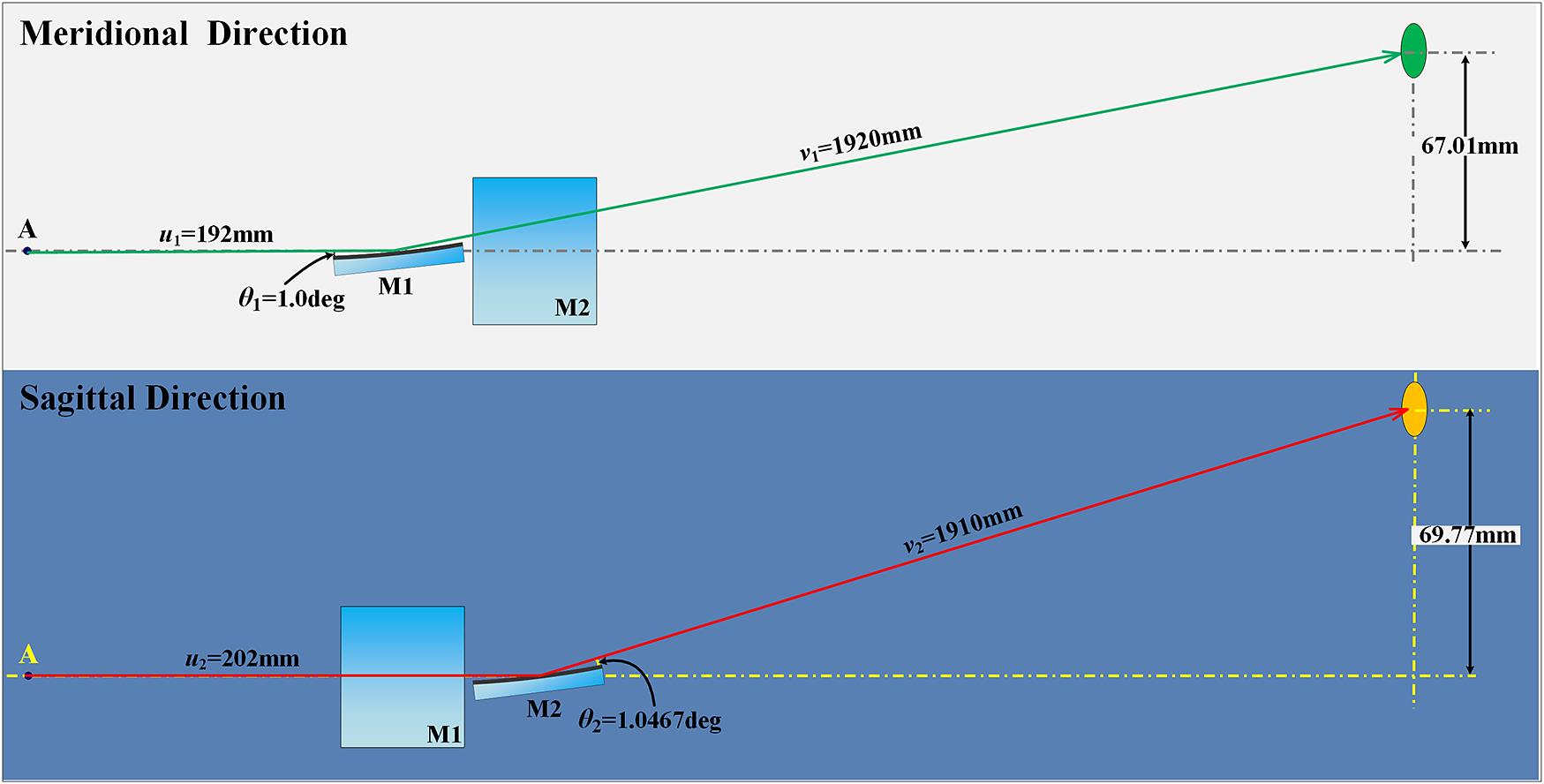
Figure 1.Schematic of the multilayer KB microscope for high-resolution Ti flash radiography.
The mirror length d was 10 mm, and the corresponding spatial resolution obtained by the Zemax simulation near-linearly decreased from 2 μm at the central field to near 7 μm within the object field of 300 μm × 300 μm in length and width. When choosing a shorter mirror length, a higher spatial resolution can be obtained, but the image intensity will be reduced. The manufacture error of the curvature radius (ΔR) leads to deviations of the best object field of view. Although It can be compensated for by changing the actual grazing angle, the reflectivity may be seriously reduced owing to the narrow angular bandwidth of the multilayer. Thus, we optimized the following three aspects: first, the concave mirrors were accurately measured by the optical profiler (Bruker ContourGT-X3) to have a mean radius of curvature of 19.5 m with a root-mean-square (RMS) variation of 0.3 m, which corresponds to the grazing angle change of ∼0.015°; second, the deviation of the grazing incidence angle at different mirror positions is within ±0.025° from the center value of 1.000° or 1.046°, and therefore the multilayer bandwidth has also been properly designed to near ±0.04° to satisfy above grazing angle changes, as detailed in Section 3; third, according to the different grazing angles in meridian and sagittal directions, two sets of multilayer mirrors were designed and fabricated respectively. Table 1 presents the final optical parameters of the instrument.
| Direction | R (m) | d (mm) | θ | u (mm) | v (mm) | M |
|---|---|---|---|---|---|---|
| Meridional Sagittal | 19.5 | 10 | 1.000° | 187.2 | 1872 | 10 |
| 1.046° | 197.2 | 1862 | 9.44 |
Table 1. Optical parameters of the multilayer KB microscope.
3. Multilayer design and fabrication
The KB microscopes can be operated at different energy bands by coating the metal single layer or X-ray multilayer on the reflected surfaces. The metal single layers (e.g., Ir or Pt) based on the total external reflection are good elements to use in the soft X-ray region. They can also respond to harder X-rays, but only at grazing angles smaller than the critical angle of the total external reflection. At this time, the lateral aberration expressed by δ = 3d2/8R + dq/R sinθ (where q is the object field) becomes larger due to the smaller grazing angle, which reduces the spatial resolution of the KB microscope[15]. Compared with a metal single layer, the multilayer coatings consisting of alternating bilayers of high-Z and low-Z materials are a better choice to obtain a high throughput at Ti characteristic lines. It can be understood by the Bragg diffraction formula that 2D sinθ = mλ, where D is the periodic thickness of the multilayer, θ is the grazing angle, m is the order of X-ray diffraction; and λ is the X-ray wavelength. In this paper, it includes two types of multilayer stacks (i.e., Co/C and W/C) with different parameters from the surface to the substrate. The Co/C and W/C are two good material pairs to obtain high reflectivity near the energy of 4.5–4.75 keV and 8 keV respectively because of the difference of optical constants. Among them, the Co/C stacks were designed to have a larger spectral bandwidth by adjusting the thickness ratio of high-Z and low-Z materials due to the existence of Ti He-like lines (∼4.75 keV) and Kα lines (∼4.5 keV) in the spectrum. Although the peak reflectivity was slightly reduced, the spectral bandwidth was effectively improved to cover the above two characteristic lines and obtain highest possible image intensity within a certain object field. The Co/C stacks working at the Ti characteristic lines have seven bilayer numbers, whose thickness is 9.15 and 8.70 nm for the grazing angles of 1.000° and 1.046°, respectively. The W/C stacks working at the Cu Kα (∼8.05 keV) characteristic line will be used for the alignment and assembly of the microscope in air by a common copper tube with 30 bilayer numbers, whose thickness is 4.77 and 4.56 nm for the grazing angles of 1.000° and 1.046°, respectively. In physics experiments, the Ti characteristic lines are directly reflected by the top Co/C bilayers; hence, the bottom W/C bilayers will not reduce the X-ray throughput. The spatial resolution is only slightly different at the Ti characteristic lines when compared with that at 8.05 keV owing to the X-ray diffraction. Furthermore, under the assumption that the self-emission X-ray spectrum is of an exponential form, the influence of 8.05 keV X-rays on the lower Ti characteristic lines can be negligible. All multilayers were deposited onto ultra-polished silica substrates with a DC magnetron sputtering system. The micro-roughness of the silica substrates measured by an optical profiler (Bruker Inc., CoutourGT-X3) was approximately 0.3 nm. The control accuracy of the multilayer thicknesses with the deposition system was approximately 0.1 nm. Figure 2 depicts the reflectivity measurements by an X-ray diffractometer (Bede D1 system) at 8.05 keV.
![]()
Figure 2.Reflectivity measurement results of the KB multilayer by the X-ray diffractometer for grazing angles of (a) 1.000° and (b) 1.046°.
The spectral response of the multilayer can also be obtained by fitting the measured reflectivity curves (Figure 3). The reflectivities of both multilayers were more than 60% at 4.75 and 4.5 keV.
![]()
Figure 3.Spectral response curves by fitting the reflectivity measurement results of the KB multilayer for grazing angles of (a) 1.000° and (b) 1.046°.
4. Microscope alignment method
The spatial resolution of the KB microscope decreased with the deviation from the central field of view because of a serious off-axis aberration. Therefore, the KB microscope must be accurately aimed to the central field of view to obtain a spatial resolution better than 5 μm. Meanwhile, for flash radiography, the backlighter position must be accurately adjusted to the incident optical axis of the KB microscope to ensure that the micro-focus source of less than 100 μm covers the diagnostic area of interest.
We developed an accurate indication method based on dual simulated balls coupling with linear guides for the KB microscope alignment (Figure 4). First, the central field of view of the KB microscope (with best resolution) was found by the imaging experiment of a metal grid using a copper X-ray tube (8.05 keV, Cu Kα line). Figure 5(a) depicts the image of a 600-mesh Au grid (43 μm period with 6–7 μm linewidth measured by scanning electron microscopy) recorded by a phosphor X-ray CCD (Photonic Science: VHR-11M) with 4096 × 3060 pixels and 9.0 × 9.0 μm pixel size. The phosphor material is Gadox:Tb with the thickness of 20 μm and the spatial resolution of 30 lp/mm. The total quantum gain at Cu Kα line is 3.5 electrons per incident X-ray photon. The exposure time was 10 min with the circuit gain of 50 to get enough image brightness. The hole with approximately 150 μm diameter in the grid was used as a reference for the best resolution. The spatial resolution defined as the distance between 10% and 90% intensity appears in Figure 5(b) by three measurements along the horizonal dotted line in Figure 5(a), which was approximately 3.0 μm in the hole center and better than 5 μm in approximately 200 μm field of view. The solid line and dash-dotted line represent simulation results of spatial resolution with and without the additional errors, respectively. The additional errors, which are mainly the pixel size of the X-ray CCD camera, the figure error, and the mirror roughness, reduce the actual resolution, especially for the central object field. We estimate that the reference hole is deviated by less than 20 μm from the central object field, which is acceptable in terms of spatial resolution. The actual magnifications in the meridional and sagittal directions were approximately 10.15× and 9.57×, respectively. Then the position of reference hole was replaced by the first simulated ball with a diameter of approximately 500 μm under the monitoring of two orthogonal visible light CCD cameras. The incident optical axis of the KB microscope is defined with the first simulated ball and the mirror center of the KB microscope as two points. Finally, the second simulated ball with a diameter of approximately 300 μm was placed on the incident optical axis to indicate the micro-focus source position. The distance between the two simulated balls was consistent with the actual application condition, which was 5.0 mm. In addition, we used a red diode laser (diameter ∼1 mm) fixed on the stainless-steel plate of the KB microscope to indicate the image point. Both simulated balls were removable from the KB microscope by two precise linear guides (as shown in Figure 4) with a repeat positioning accuracy of up to 20 μm. The shielding block at the front of the KB microscope was made of lead–antimony alloy, which is used to shield high-energy background noise.
![]()
Figure 4.Alignment parts of the multilayer KB microscope based on dual simulated balls.
![]()
Figure 5.(a) Spatial resolution testing image and (b) calibrated result of the 600-mesh Au grid backlighted by a copper X-ray tube.
5. Experiment on SG-II Update
The microscope alignment was performed in the following steps at the SG-II Update facility for a fast-ignition study. Under the instruction of the target view system[16], the microscope was aligned by an x–y–z translation stage until the first simulated ball was moved to the desired diagnostic position. The position of the second simulated ball at this time was used as the focus point of the picosecond-pulse laser beam. The image plate (Fuji, BAS-SR2025) was then placed at the position indicated by the red diode laser. Lastly, the ball pointer and the diode laser were removed from two linear guides.
Figure 6 shows the test result of the microscope by Ti flash radiography of the indirect-driven gold cone target. The width of the gold cone top was approximately 32 μm with a cone angle of approximately 40°. Affected by the repeated positioning accuracy of linear guide and vacuum pumping after alignment, the brightest position of X-ray backlighter has a deviation of about 20 μm from the central area to be diagnosed, and its influence on spatial resolution can be ignored as seen from Figure 5(b). An effective backlighter area of flash radiography with approximately 80 μm diameter was produced by the picosecond-pulse laser beam of the SG-II Update facility, which covers the entire area on left side of the cone top that we want to diagnose.
![]()
Figure 6.Test result of the KB microscope by Ti flash radiography of the indirect-driven gold cone target.
6. Conclusion
High-resolution X-ray flash radiography of the Ti characteristic lines with a multilayer KB microscope has been reported herein. The multilayer design, including Co/C and W/C stacks, was optimized to obtain a high reflection efficiency of the Ti characteristic lines of more than 60% while meeting the precise alignment requirement at the Cu Kα line. The accurate simultaneous indication of the center field of view and backlighter position was realized by dual simulated balls. A spatial resolution of 3–5 μm within ±100 μm field of view was achieved in the X-ray experiments. The imaging result of the Au-coned CH shell target on the SG-II Update demonstrated the feasibility for Ti flash radiography. The microscope may also be suitable for backlit imaging with higher X-ray energies if some improvements are made, such as optimizing the multilayer structure to increase the reflectivity for higher X-ray energy or using aspheric mirrors to obtain higher collection efficiency while ensuring the spatial resolution.
References
[1] S. Atzeni, J. Meyer-ter-Vehn. International Series of Monographs on Physics(2004).
[2] B. Han, F. Wang, D. Salzmann, J. Zhong, G. Zhao. High Power Laser Sci. Eng, 9, e9(2021).
[3] L. A. Pickworth, B. A. Hammel, V. A. Smalyuk, A. G. MacPhee, H. A. Scott, H. F. Robey, O. L. Landen, M. A. Barrios, S. P. Regan, M. B. Schneider, M. Hoppe, T. Konut, D. Holunga, C. Walters, B. Haid, M. Dayton. Phys. Rev. Lett, 117, 035001(2016).
[4] E. Brambrink, S. Baton, M. Koenig, R. Yurchak, N. Bidaut, B. Albertazzi, J. E. Cross, G. Gregori, A. Rigby, E. Falize, A. Pelka, F. Kroll, S. Pikuz, Y. Sakawa, N. Ozaki, C. Kuranz, M. Manuel, C. Li, P. Tzeferacos, D. Lamb. High Power Laser Sci. Eng, 4, e30(2016).
[5] A. Morace, L. Fedeli, D. Batani, S. Baton, F. N. Beg, S. Hulin, L. C. Jarrott, A. Margarit, M. Nakai, M. Nakatsutsumi. Phys. Plasmas, 21, 102712(2014).
[6] H. Sawada, S. Lee, T. Shiroto, H. Nagatomo, Y. Arikawa, H. Nishimura, T. Ueda, K. Shigemor, A. Sunahar, N. Ohnishi. Appl. Phys. Lett, 108, 254101(2016).
[7] C. Stoeckl, T. Filkins, R. Jungquist, C. Mileham, N. R. Pereira, S. P. Regan, M. J. Shoup, W. Theobald. Rev. Sci. Instrum, 89, 10G124(2018).
[8] L. C. Jarrott, M. S. Wei, C. McGuffey, A. A. Solodov, W. Theobald, B. Qiao, C. Stoeckl, R. Betti, H. Chen, J. Delettrez, T. Döppner, E. M. Giraldez, V. Y. Glebov, H. Habara, T. Iwawaki, M. H. Key, R. W. Luo, F. J. Marshall, H. S. McLean, C. Mileham, P. K. Patel, J. J. Santos, H. Sawada, R. B. Stephens, T. Yabuuchi, F. N. Beg. Nat. Phys, 12, 499(2016).
[9] W. Theobald, A. A. Solodov, C. Stoeckl, K. S. Anderson, F. N. Beg, R. Epstein, G. Fiksel, E. M. Giraldez, V. Y. Glebov, H. Habara. Nat. Commun, 5, 5785(2014).
[10] P. Kirkpatrick, A. V. Baez. J. Opt. Soc. Am, 38, 766(1948).
[11] L. A. Pickworth, J. Ayers, P. Bell, N. F. Brejnholt, J. G. Buscho, D. Bradley, T. Decker, S. Hau-Riege, J. Kilkenny, T. McCarville, T. Pardini, J. Vogel, C. Walton. Rev. Sci. Instrum, 87, 11E316(2016).
[12] F. J. Marshall, R. E. Bahr, V. N. Goncharov, V. Y. Glebov, B. Peng, S. P. Regan, T. C. Sangster, C. Stoeckl. Rev. Sci. Instrum, 88, 093702(2017).
[13] S. Z. Yi, Z. Zhang, Q. S. Huang, Z. Zhang, Z. S. Wang, L. Wei, D. X. Liu, L. F. Cao, Y. Q. Gu. Rev. Sci. Instrum, 89, 036105(2018).
[14] W. TheobaldOMEGA Laser Facility Users' Group Workshop. , in ().(2009).
[15] S. Z. Yi, B. Z. Mu, X. Wang, J. T. Zhu, L. Jiang, Z. S. Wang, P. F. He. Chin. Opt. Lett, 12, 013401(2014).
[16] L. Ren, P. Shao, D. Zhao, Y. Zhou, Z. Cai, N. Hua, Z. Jiao, L. Xia, Z. Qiao, R. Wu, L. Ji, D. Liu, L. Ju, W. Pan, Q. Li, Q. Ye, M. Sun, J. Zhu, Z. Lin. High Power Laser Sci. Eng, 6, e10(2018).


Set citation alerts for the article
Please enter your email address

© Copyright 2018-2021 | Chinese Laser Press. All Rights Reserved 沪ICP备15018463号-20