
[in Chinese], [in Chinese], [in Chinese], [in Chinese], [in Chinese]. Perfect electromagnetic and sound absorption via subwavelength holes array[J]. Opto-Electronic Advances, 2018, 1(8): 180013
- Opto-Electronic Advances
- Vol. 1, Issue 8, 180013 (2018)
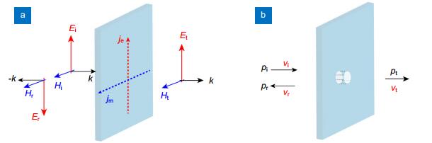
Fig. 1. Boundary conditions for the electromagnetic and acoustic waves on a thin plate.(a ) Electric and magnetic fields matching. (b ) Pressure and velocity matching.
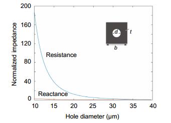
Fig. 2. Normalized impedance versus the hole diameter d at a frequency of 10 kHz.b =t =100 μm.
Fig. 3. Normalized impedance of micro-perforated plate.d =38.5 μm, b =t =100 μm.
Fig. 4. Acoustic Salisbury and Jaumann absorbers.(a ) Schematic of the configuration of the multilayered acoustic absorbers. (b ) Absorption spectra of the acoustic Salisbury and Jaumann absorbers.
Fig. 5. Angular dependence of the Jaumann absorber.As the incidence angle is increased from the 0° to 80°, the absorption valley position at about 14 kHz shifts to higher frequencies, accompanying with a small decrease of the absorption efficiency.
Fig. 6. Acoustic coherent perfect absorber.(a ) Absorption spectra of the coherent perfect absorber. (b ) Normalized impedance at different frequencies.
Fig. 7. Variation in the absorption under different coherent conditions.(a ) Absorption versus frequency f with path difference of l =0.2 m.
(b ) Absorption versus l at f = 10 kHz.
Fig. 8. Schematic of the acoustic multilayer.In each layer, there are two counter-propagating waves with amplitudes of A and B . These amplitudes are connected with matrix shown in the text.


Set citation alerts for the article
Please enter your email address

© Copyright 2018-2021 | Chinese Laser Press. All Rights Reserved 沪ICP备15018463号-20