State Key Laboratory of Optical Technologies on Nano-Fabrication and Micro-Engineering, Institute of Optics and Electronics, Chinese Academy of Sciences, Chengdu, 610209, China
Broadband sound absorption at low frequency is notoriously difficult because the thickness of the absorber should be proportional to the working wavelength. Here we report an acoustic metasurface absorber following the recent theory developed for electromagnetics. We first show that there is an intrinsic analogy between the impedance description of sound and electromagnetic metasurfaces. Subsequently, we demonstrated that the classic Salisbury and Jaumann absorbers can be realized for acoustic applications with the aid of micro-perforated plates. Finally, the concept of coherent perfect absorption is introduced to achieve ultrathin and ultra-broadband sound absorbers. We anticipate that the approach proposed here can provide helpful guidance for the design of future acoustic and electromagnetic devices.
Perhaps all things around us are some types of waves, such as the light waves, acoustic waves, matter waves and even gravitational waves. The absorption or dissipation of the energy carried by these waves is of great importance in many applications ranging from energy harvest and information exchange to radar wave and sound noise control1-8. Among the various types of waves, the electromagnetic and acoustic waves share many similarities. In the last decades, the two disciplines have borrowed concepts from each other to grow up alternately. For example, the time-reversed sub-diffraction focusing technique was first developed by the acousticians and then utilized in the optical domain to break the diffraction limit9-12. On the other hand, the hyperlens was originally created in the optical domain and then introduced to acoustic research13, 14. Recently, the concept of metasurface, an artificially structured thin film with property on demand, has become a hot spot in both the electromagnetic and acoustic regimes15-18. It is, however, surprising that many metasurface concepts such as Salisbury and Jaumann absorbers in the electromagnetic design have not been extended into the acoustic domain. Furthermore, although ultrathin and ultra-broadband electromagnetic absorbers have been realized19, 20, similar thin absorbers are still difficult to obtain for acousticians4, 17.
In this paper, we theoretically compared the boundary conditions for electromagnetic and acoustic metasurfaces. Similar to electromagnetic metasurface absorber, we show that various acoustic absorbers can be achieved using the effective impedance of deep-subwavelength perforated rigid plate (may be approximated by steel). In particular, an ultra-broadband and thin acoustic perfect absorber is demonstrated under coherent condition, showing excellent performance comparable to its electromagnetic counterpart.
Results
Analogy between the boundary conditions of electromagnetic and acoustic waves
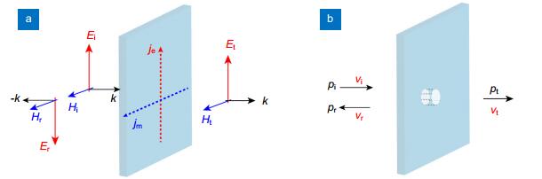
First of all, the boundary conditions for electromagnetic metasurface are considered. As shown in Fig. 1(a), the tangential components of the electric and magnetic fields are continuous at the interface between two half-infinite materials. When a non-magnetic impedance sheet with zero thickness is placed at this interface21, the boundary conditions should be rewritten as
Figure 1.Boundary conditions for the electromagnetic and acoustic waves on a thin plate.(a) Electric and magnetic fields matching. (b) Pressure and velocity matching.
where i, r and t denote the incidence, reflection and transmission, $\parallel $ represents the tangential components, ${\mathit{\boldsymbol{\hat n}}}$ is the unit vector along the normal direction, Ys, em is the electric sheet inductance of the metasurface.
Since ${\mathit{\boldsymbol{E}}}$ and ${\mathit{\boldsymbol{H}}}$ are related via the Faraday's law,
where rem and tem are the reflection and transmission coefficients defined by the electric fields, Y1,em and Y2,em are the inductances of two materials in the left and right sides.
Similar to the electromagnetic case, the boundary conditions for an acoustic impedance sheet (Fig. 1(b)) has the form of
where v and p are the velocity and pressure of the sound perturbation. While equation (4) is a direct result of the mass conservation, equation (5) is obtained by defining the effective sheet impedance
Assuming that the background is filled with air, the impedance can be written as ${Z_{{\text{1, }}\;{\text{ac}}}} = {Z_{{\text{2, }}\;{\text{ac}}}} = \rho c/\cos \theta $, where θ is the incidence angle, c is the velocity of acoustic wave. Combing equations (4)–(7), one can obtain the following expression
Interestingly, equations (3) and (8) have very similar form, except that the admittance in equation (3) is replaced by the impedance in equation (8). This similarity implies that both the acoustic and electromagnetic problems in metasurfaces can be solved by transfer matrix, along with proper boundary conditions.
Impedance sheet realized by micro-perforated plate
In the above discussion, an arbitrary sheet impedance is assumed without considering its practical realization. In the following, the effective impedance of micro-perforated plate (MPP) is utilized in the design of various acoustic absorbers. It should be noted that although the MPP absorbers have been intensively studied after its invention by Maa in 1970s22-24, its intrinsic similarity with electromagnetic absorber such as Salisbury and Jaumann absorbers has seldom been studied25-27. In this paper, we show that the concept borrowed from electromagnetics is very efficient in the design of acoustic devices.
In general, the effective impedance of a micro-tube perforated in a rigid plate should be calculated using computational fluid dynamics (CFD)23. However, when the tube is short compared to the wavelength, the effective impedance can be approximately analyzed using the equation of aerial motion
where v is particle velocity, $\omega = 2{\rm{\pi }}f$ the angular frequency, Δp the sound pressure between the ends of the tube, t the thickness of the tube (equal to that of the panel), ρ0 the density of air, η the coefficient of viscosity, and r1 the radius vector of cylindrical coordinates inside the tube. The specific acoustic impedance can be obtained as
where $\kappa = {r_0}\sqrt {{\rho _0}\omega /\eta } $ is the perforate constant, r0 is the radius of the tube, J1 the Bessel function of the first kind, J0 the Bessel function of zeroth kind. The normalized impedance can be obtained as
where $\sigma = {A_{{\text{hole}}}}/{A_{{\text{cell}}}}$ is the perforation ratio in area. In practical applications, the hole's dynamic end correction should be considered, leading to the following sheet impedance
where $\beta $= 0.613 is an empirical parameter23.
The normalized impedance at f=10 kHz for different hole diameters is plotted in Fig. 2. Clearly, as the increase of the hole diameter, the impedance drops down rapidly. When the hole is extremely small, the impedance tends to be infinite, with all sound wave being reflected. The frequency-dependent impedance of a MPP metasurface is shown in Fig. 3, where the geometric parameters are fixed as d=38.5 μm and b=t=100 μm. Evidently, the resistance is almost independent of the frequency, while the reactance is proportional to the frequency.
Figure 2.Normalized impedance versus the hole diameter d at a frequency of 10 kHz.b=t=100 μm.
From above results, it is clear that a thin micro-perforated plate bears similar properties with the resistive sheet (thin metal film) in the electromagnetic applications25. Combining with the similarity in boundary conditions, it can be concluded that the acoustic waves can be controlled using electromagnetic-inspired approaches. Furthermore, it is expected that more complex sheet impedance is possible by combing the micro-perforated plate with cavities or other resonant structures28.
Acoustic Salisbury and Jaumann absorbers
As the first step to demonstrate the intrinsic connection between the electromagnetic and acoustic metasurface, the acoustic-type Salisbury25, 29 and Jaumann30 absorbers are investigated. As depicted in Fig. 4, the absorption spectra of two optimized absorbers are calculated using transfer matrix method (see methods). Theoretically, the physical mechanism behind the absorption is the multiple interference between successive reflections31. Although only theoretical results are given here, previous experiments agree well with our theory24, indicating that the following discussion is sound and robust.
Figure 4.Acoustic Salisbury and Jaumann absorbers.(a) Schematic of the configuration of the multilayered acoustic absorbers. (b) Absorption spectra of the acoustic Salisbury and Jaumann absorbers.
For the Salisbury-type absorber, there is only one micro-perforated plate (labelled as MPP-1) separated from the rigid body with a distance of h1 =48 mm. The geometric parameters of MPP-1 is d1=38.5 μm and b=t =100 μm. For the Jaumann-type absorber, there are four MPPs placed successively with distance h1=h2=h3=h4=12 mm. The thickness t and period b are equal for all these MPPs, while the hole diameters are d1=38.5 μm, d2=40 μm, d3=45 μm and d4=50 μm. Note that the one-layer Salisbury and four-layer Jaumann structures are two representing examples. For the two- and three-layer structures, the bandwidth would be larger than the one-layer but smaller than the four-layer cases. Similar to the electromagnetic case, the thickness mainly determines the absorption frequency. As the thickness becomes larger, the frequency will become smaller.
As illustrated in Fig. 5, the dependence of the acoustic Jaumann absorber on the incidence angle θ is also investigated. Similar to its electromagnetic counterpart, the absorption efficiency would decrease as the rise of the incidence angle although most is larger than 90% for θ < 60°. In addition, we noted that the angle dependence is similar to the transverse electric (TE) mode, rather than the transverse magnetic (TM) mode, as can be derived from the boundary conditions.
Figure 5.Angular dependence of the Jaumann absorber.As the incidence angle is increased from the 0° to 80°, the absorption valley position at about 14 kHz shifts to higher frequencies, accompanying with a small decrease of the absorption efficiency.
Anyway, the results shown in Figs. 4 and 5 resemble that for classic electromagnetic absorbers1. Consequently, we expect that the theory of the recent developed electromagnetic absorbers3, 32 can be leveraged to design acoustic absorbers in a more sophisticated way.
Coherent perfect absorption of acoustic wave
Different from traditional absorbers, coherent perfect absorption (CPA) is a process that requires two or more coherent inputs19, 20, 33-37. Owing to the revision of the operation condition, previous limitation on the bandwidth and absorber thickness, as set by the casualty and Kramers-Kronig relations38, can be eliminated19, 39. This broadband coherent absorption characteristic seems a surprise since CPA was thought as a time-reversed process of lasing, which is intrinsically narrowband40. Nevertheless, from the view point of electrodynamics, this broadband absorption can be indeed treated as the time-reversed process of the radiating current sheet19, which is not limited in bandwidth. Although CPA is of particular importance for electromagnetic applications, its realization in acoustic region is hampered by the absence of proper lossy materials17. Although there are some attempts to design acoustic CPA41, the results seems not so satisfactory because only narrowband absorption can be achieved.
Figure 6 illustrated the absorption spectrum under CPA condition. The hole diameter of the MPP is 32.1 μm, while the thickness and period are both 100 μm. As we expected, the absorption can be as high as 99% at frequencies below 10 kHz, which is very similar to the ultra-broadband electromagnetic CPA19. It should be noted that the normalized impedance for the MPP at CPA condition is nearly twice that of air, while in the electromagnetic case the impedance is only half. This difference is a direct result of the different definition of impedance in acoustics and electromagnetics. Furthermore, since the amplitude of the acoustic wave is defined using the pressure p, the CPA condition requires s=-1 (asymmetric mode), which is also contrary to the electromagnetic CPA19.
Figure 6.Acoustic coherent perfect absorber.(a) Absorption spectra of the coherent perfect absorber. (b) Normalized impedance at different frequencies.
One of the intrinsic advantages of CPA over traditional absorbers lies in the fact that the absorption can be easily tuned by varying the phase difference between the left and right inputs (l). Similar to the electromagnetic counterpart19, the absorption may be written as:
$
A = 1 - {\sin ^2}(\frac{{\omega l}}{{2{v_0}}}),
$
where v0 = 343 m/s is the velocity of sound in air.
As shown in Fig. 7(a), when the path difference is fixed to be 0.2 m, the absorption spectra vary rapidly with the sound frequency. Note that the absorption at very low frequency is always near 100%, implying that this technique is very efficient for the absorption at low frequency. Figure 7(b) depicts the absorption at 10 kHz for various path difference, where the ratio of the minimum to maximum can be as smaller as 2e-5, which is beneficial to the coherent acoustic modulators. Similar to the concept of "controlling light with light"42, the acoustic CPA can be also leveraged to realize "controlling sound with sound" on metasurfaces.
Figure 7.Variation in the absorption under different coherent conditions.(a) Absorption versus frequency f with path difference of l=0.2 m.
(b) Absorption versus l at f = 10 kHz.
In summary, we have unified the theory of electromagnetic and acoustic absorbers in the context of metasurfaces. It is demonstrated unambiguously that the theory of electromagnetic absorbers can provide useful guidance for acoustic researches. The ultra-broadband acoustic CPA proves that previous judgment about sound absorption, especially at low frequency, is not accurate17.
It should be pointed out that the impedance of the MPP is mainly determined by the radius of the deep-subwavelength-scale holes, which are also of particular importance in electromagnetic scenarios such as the extraordinary optical transmission43 and frequency selective surfaces44. As the operational frequency rises, the holes need to be scaled down to maintain the required impedance and there will be huge challenges to fabricate such small holes in a large area. Meanwhile, the accuracy of Maa's model needs further experimental investigation at higher frequency. Nevertheless, there is no problem if we focus on the low-frequency regime, which is just the difficult point of traditional approaches. Potential applications may be found in the noise control in both air and water environments.
Method of transfer matrix for the multilayered acoustic absorber
Similar to the electromagnetic case, the multilayered acoustic structure can be calculated efficiently using the transfer matrix. As depicted in Fig. 8, the coefficients of the counter-propagating acoustic waves are denoted as A and B, while the two pairs of quantities can be written as
Figure 8.Schematic of the acoustic multilayer.In each layer, there are two counter-propagating waves with amplitudes of A and B. These amplitudes are connected with matrix shown in the text.
is the transition matrix of the metasurface, while
is the propagation matrix of the mth layer. Here $k = \cos (\theta )\omega /c$ is the normal component of the acoustic wave number.
Obviously, the amplitudes of acoustic waves at the outmost layer can be calculated from the innermost directly. Since there is a rigid body acting as a perfect reflector, the final form of the transfer matrix can be written as
where Mm=M1,mM2,m is the transfer matrix of a pair of air and metasurface. The reflection and absorption coefficients can be then calculated as
Acknowledgements
We acknowledge the financial support by 973 Program of China under contract No. 2013CBA01700 and the National Natural Science Foundation of China under contract No. 61622509 and 61575203.
Competing interests
The authors declare no competing financial interests.
References
[1] KnottE FShaefferJ FTuleyM TRadar Cross Section 2nd ed (SciTech Publishing, Raleigh, North Carolina, 2004)Knott E F, Shaeffer J F, Tuley M T. Radar Cross Section 2nd ed (SciTech Publishing, Raleigh, North Carolina, 2004).
[11] L W Chen, Y Zhou, M X Wu, M H Hong. Remote-mode microsphere nano-imaging: new boundaries for optical microscopes. Opto-Electron Adv, 1, 170001(2018).
[44] MunkB AFrequency Selective Surfaces: Theory and Design (Wiley, New York, 2000)Munk B A. Frequency Selective Surfaces: Theory and Design (Wiley, New York, 2000).