• Journal of Semiconductors
  • Vol. 43, Issue 6, 062801 (2022)
Huabin Yu, Muhammad Hunain Memon, Hongfeng Jia, Haochen Zhang, Meng Tian, Shi Fang, Danhao Wang, Yang Kang, Shudan Xiao, Shibing Long, and Haiding Sun
Author Affiliations
  • School of Microelectronics, University of Science and Technology of China, Hefei 230026, China
  • show less
    DOI: 10.1088/1674-4926/43/6/062801 Cite this Article
    Huabin Yu, Muhammad Hunain Memon, Hongfeng Jia, Haochen Zhang, Meng Tian, Shi Fang, Danhao Wang, Yang Kang, Shudan Xiao, Shibing Long, Haiding Sun. A 10 × 10 deep ultraviolet light-emitting micro-LED array[J]. Journal of Semiconductors, 2022, 43(6): 062801 Copy Citation Text show less
    (Color online) (a) Schematic of a fabricated DUV μ-LED array and (b) its cross-section of the DUV μ-LED array and (c) the profile of the sidewall and θ is the inclination angle of the sidewall.
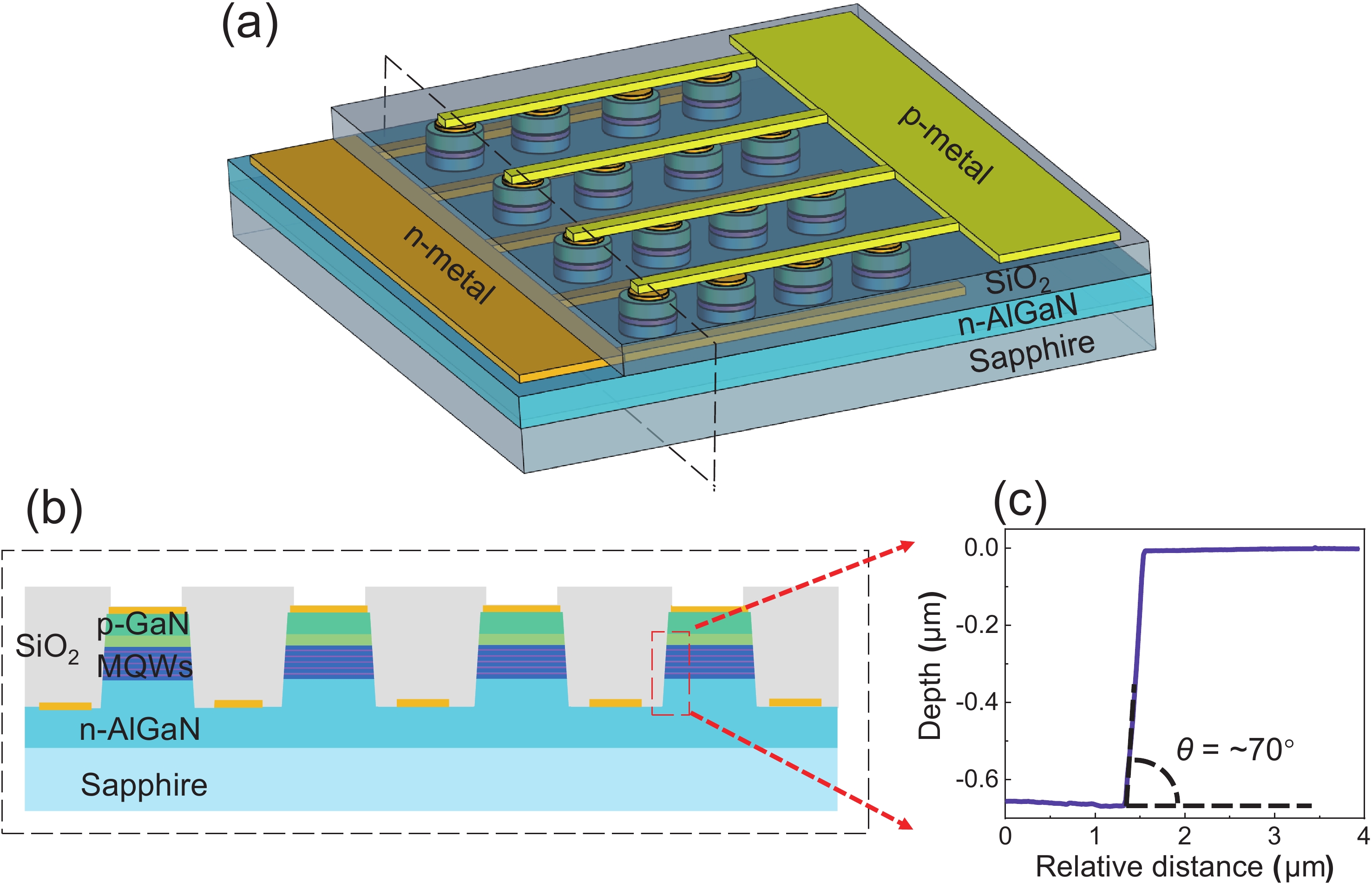
    Fig. 1. (Color online) (a) Schematic of a fabricated DUV μ-LED array and (b) its cross-section of the DUV μ-LED array and (c) the profile of the sidewall and θ is the inclination angle of the sidewall.
    (Color online) (a) The current–voltage (I–V) characteristic of the DUV LEDs. The inset shows the corresponding logarithmic plot. (b) The spectra of the DUV LEDs operating at the driving current of 100 mA.
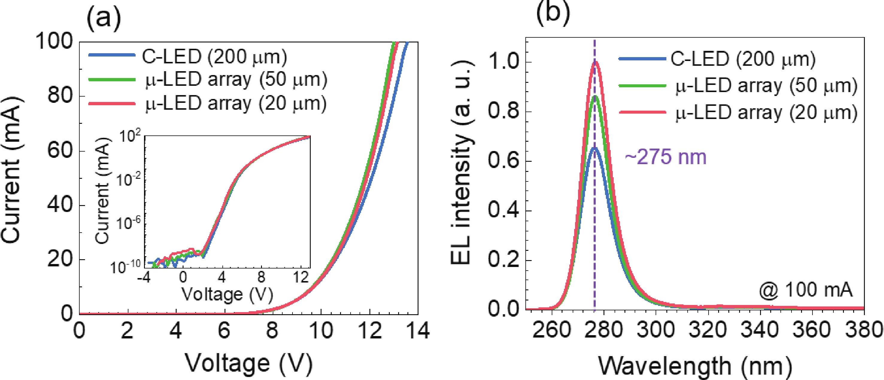
    Fig. 2. (Color online) (a) The current–voltage (IV) characteristic of the DUV LEDs. The inset shows the corresponding logarithmic plot. (b) The spectra of the DUV LEDs operating at the driving current of 100 mA.
    (Color online) (a) The light output power (LOP), (b) the external quantum efficiency (EQE), (c) the wall-plug efficiency, and (d) the LEE enhancement factor of the DUV LEDs at different currents for the three investigated devices.
    Fig. 3. (Color online) (a) The light output power (LOP), (b) the external quantum efficiency (EQE), (c) the wall-plug efficiency, and (d) the LEE enhancement factor of the DUV LEDs at different currents for the three investigated devices.
    (Color online) Electric field distributions for the light propagation paths of the TM-polarized light when the dipole source at (a) the center of the mesa and (b) the edge of the mesa. The LEEs for the (c) TE- and (d) TM-polarized light as a function of the position of the dipole source for the C-LED, μ-LED (50 μm), and μ-LED (20 μm), respectively. The insets of the (c) and (d) are the device schematic which indicates the position change of the dipole source.
    Fig. 4. (Color online) Electric field distributions for the light propagation paths of the TM-polarized light when the dipole source at (a) the center of the mesa and (b) the edge of the mesa. The LEEs for the (c) TE- and (d) TM-polarized light as a function of the position of the dipole source for the C-LED, μ-LED (50 μm), and μ-LED (20 μm), respectively. The insets of the (c) and (d) are the device schematic which indicates the position change of the dipole source.
    (Color online) (a) Far-field patterns for the C-LED, the μ-LED array (50 μm), and the μ-LED array (20 μm) at 100 mA. (b) The divergence angle of the far-field patterns. The schematic illustrations of light propagation characteristics in (c) the C-LED and (d) the μ-LED array.
    Fig. 5. (Color online) (a) Far-field patterns for the C-LED, the μ-LED array (50 μm), and the μ-LED array (20 μm) at 100 mA. (b) The divergence angle of the far-field patterns. The schematic illustrations of light propagation characteristics in (c) the C-LED and (d) the μ-LED array.
    Huabin Yu, Muhammad Hunain Memon, Hongfeng Jia, Haochen Zhang, Meng Tian, Shi Fang, Danhao Wang, Yang Kang, Shudan Xiao, Shibing Long, Haiding Sun. A 10 × 10 deep ultraviolet light-emitting micro-LED array[J]. Journal of Semiconductors, 2022, 43(6): 062801
    Download Citation