
Bin Wu, Xuri Wang. Inertial Navigation Aided Image Feature Matching Method[J]. Laser & Optoelectronics Progress, 2020, 57(10): 101509
- Laser & Optoelectronics Progress
- Vol. 57, Issue 10, 101509 (2020)
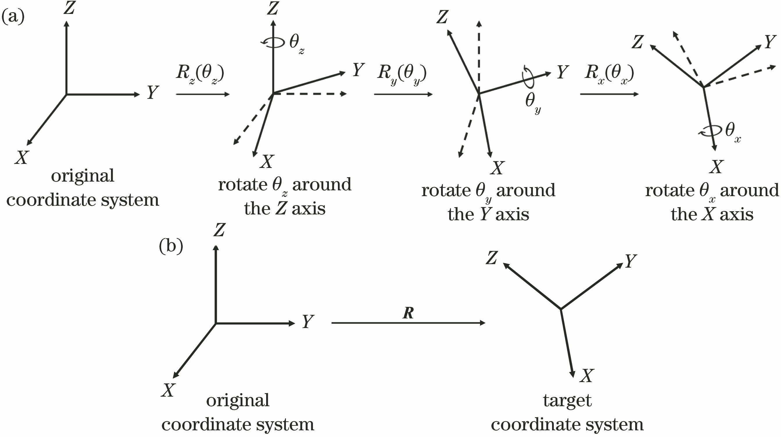
Fig. 1. Process of three-dimensional rotation. (a) Process of rotation; (b) three-dimensional rotation

Fig. 2. Process of coordinate transformation
Fig. 3. Calculation process of displacement variation in navigation coordinate system
Fig. 4. Epipolar geometric constraint
Fig. 5. Process of inertial navigation aided image feature matching
Fig. 6. Experimental equipment
Fig. 7. Source images. (a) First image of experimental table; (b) second image of experimental table; (c) first image of laboratory; (d) second image of laboratory; (e) first image of office; (f) second image of office
Fig. 8. Brute-force match results of three sets of images
Fig. 9. Possible areas. (a) Four feature points selected in the first image of experimental table; (b) possible areas corresponding to the feature points in the first image of experimental table; (c) four feature points selected in the first image of laboratory; (d) possible areas corresponding to the feature points in the first image of laboratory; (e) four feature points selected in the first image of office; (f) possible areas corresponding to the feature points in the first image of office
Fig. 10. Match results of three sets of images after adding constraints
Fig. 11. Match results of three sets of images after removing outliers by RANSAC
|
Table 1. Rotation matrix
|
Table 2. Translation vector
|
Table 3. Fundamental matrix
|
Table 4. Matching results of three sets of images

Set citation alerts for the article
Please enter your email address
© Copyright 2018-2021 | Chinese Laser Press. All Rights Reserved 沪ICP备15018463号-20