1Tianjin Key Laboratory of Integrated Opto-electronics Technologies and Devices, School of Precision Instruments and Opto-electronics Engineering, Tianjin University, Tianjin 300072, China
Zhuang Ma, Xiaoyan Zhou, Lin Zhang, "Phase regimes of parity-time-symmetric coupled-ring systems at exceptional points," Photonics Res. 10, 2374 (2022)
Copy Citation Text
The optical coupled resonant system consisting of an integrated resonator with gain and a resonator with loss provides an excellent platform to create exceptional points (EPs) in non-Hermitian systems. Most previous studies have focused on the striking intensity feature of EPs, but its phase response is seldom investigated. In this work, we present a thorough study on the phase response of an EP system. Intriguingly, the phase response exhibits distinct behavior depending on the ordering of the ring resonators: when the input light in a bus waveguide is coupled directly or indirectly to the ring with a gain, the phase response is featured by nonmonotonic transition and monotonic transition, respectively. We also prove that the newly identified phase features are theoretically guaranteed. These phase responses produce unique group delays that have never been found in other coupled resonant systems. The results deepen our understanding on EPs in non-Hermitian systems and are potentially useful for practical applications exploiting phase features.
1. INTRODUCTION
In quantum mechanics, physical observables are represented by Hermitian operators. In this regard, Hermitian systems must exhibit real eigenvalues and orthogonal eigenstates. Compared with Hermitian systems, non-Hermitian systems that have interactions with the environment in the form of matter or energy exchange exhibit complex eigenvalues in general [1–6]. In 1998, Bender and Boettcher first proposed that non-Hermitian systems can possess real spectra under the condition of parity-time (PT) symmetry, i.e., the corresponding Hamiltonian must commute with the PT operator [7]. Yet this condition alone cannot guarantee a real eigenvalue, as the Hamiltonian can undergo an abrupt phase transition and enter the so-called PT-symmetry-breaking regime beyond certain points in the parameter space, where both eigenvalues and eigenstates coalesce, known as the exceptional points (EPs).
Ordinated from quantum mechanics, PT symmetry and EPs in optical systems have drawn great research attention, as this theory can be readily formulated with the quantum potential replaced by optical index profiles [8], leading to a series of applications, including optical gyroscopes [9–15], single-mode lasers [16–21], unidirectional emission of lasing [22,23], nonreciprocal optical transmission [24–26], and optical sensing [27–31]. Among various platforms, integrated coupled microring resonators (CMRs) have been favored to experimentally investigate rich EP physics due to their unique advantages in scalability and flexibility to control optical parameters [32–35]. Recent works have shown that CMRs working in the PT-symmetric regime can achieve greatly enhanced rotation sensitivity [11–14], stable single-mode laser operation [16–20], and nanoparticle sensing [27–30], exploiting the extraordinary properties of intensity response around the EP. Compared with the striking intensity feature, its counterpart, the phase response, at EPs is seldom investigated, without which one is precluded from a comprehensive understanding of PT-symmetric systems. In practice, it is believed that the phase response at EPs is equivalently important, because one usually operates coupled resonant systems close to EP conditions (which can hardly reach an EP) and thus have a certain bandwidth around an EP frequency [36]. This means that a spectral phase profile associated with EP or near-EP devices needs to be identified and understood.
In this work, we present a detailed study of the phase response at EPs in the PT-symmetric system based on CMRs. The system is modeled with coupled mode theory (CMT) and is classified into four coupling regimes according to whether each single ring is overcoupled or undercoupled [37]. The results show that the phase response is highly dependent on the directionality of the light flow: when the input light is first coupled into the ring with gain from the bus waveguide, the peak-to-peak values of the phase spectra () that represent the maximum phase shift in a band are always less than for the four coupling regimes, although there is a difference in ; on the other hand, when the ring with loss is directly coupled with the input bus waveguide, is always regardless of the coupling regimes of the system. We prove these conclusions theoretically and briefly discuss the impact of fabrication errors on the device for practical applications. The newly identified phase responses produce unique group delays that have never been found in other coupled resonant systems.
Sign up for Photonics Research TOC. Get the latest issue of Photonics Research delivered right to you!Sign up now
2. MODELING AND RESULTS
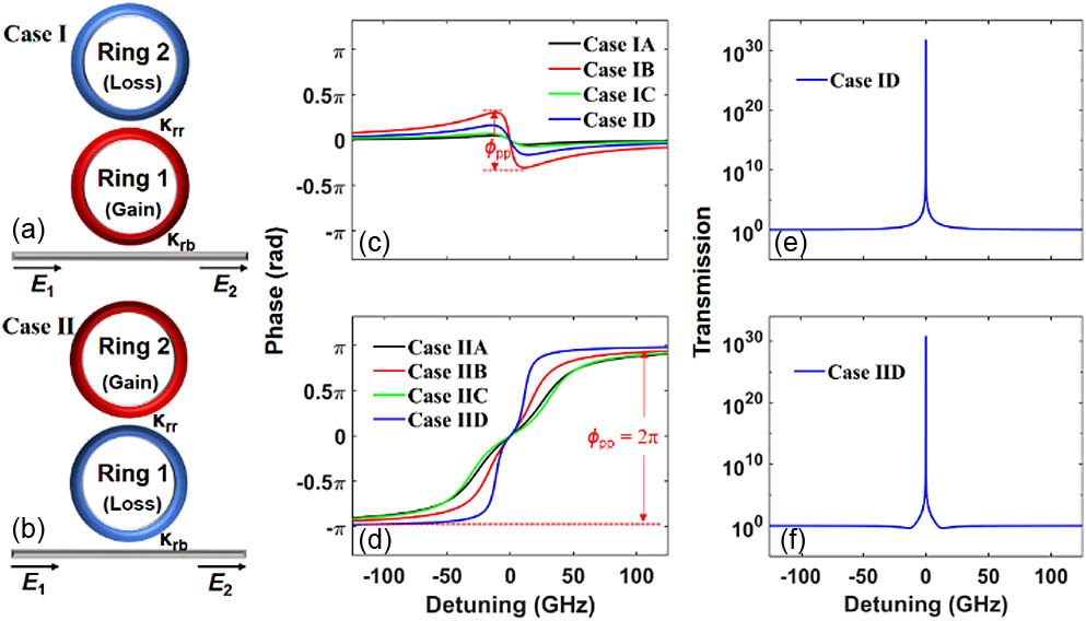
Figure 1(a) shows a schematic of typical PT-symmetric systems, which consist of two coupled rings and a bus waveguide. We name the ring directly coupled with the input bus waveguide Ring 1, and the other one Ring 2. These rings are identical in every respect except that one is with gain, while the other one is with loss [11,12,24]. We note that most EP-related phenomena have been studied in this configuration, but there is certainly another way to set up the system, as shown in Fig. 1(b). We name these two configurations Case I and Case II, respectively, according to whether the Ring 1 is amplified or not, as shown in Figs. 1(a) and 1(b). In fact, the Case II is found to be dramatically different from the Case I, as in the following.
Figure 1.(a) and (b) Schematics of the PT-symmetric systems in Case I and Case II. (c) and (d) four phase responses of Case I and Case II. values in Case IB and Case IIB are labeled out as examples. (e) and (f) Amplitude responses of Case ID and Case IID. Detailed information about A, B, C, D is in the main text.
For Case I, the fields evolve in time according to the coupled mode equations as follows [11,12,24]: where is the electric field at the input port; () is the group velocity of the th ring; () is the radius of the th ring; () is the energy amplitude in the th ring; () is the resonant angular frequency of the th ring; and () represents the gain (loss) in the th ring, respectively. The two rings have the same radius, i.e., , the same group velocity, i.e., , and the same resonant angular frequency, i.e., . is the mutual coupling between the ring and the bus waveguide, which is related to the ring-waveguide power coefficient by , and is the mutual coupling between the rings, which is related to the ring–ring power coupling coefficient by [38].
When , this system is PT-symmetric. Meanwhile, when , this system is at EPs with degenerated eigenvalues. The electric field in the through port is given by
Solving Eq. (1) by letting , we obtain the transfer function at EPs for the system,
The phase response is given by
For Case II, the form of the coupled mode equations is the same as in Case I, and the difference is that and in Case I, while and in Case II, depending on which ring resonator (with gain or loss) is placed close to the bus waveguide. Similarly, we obtain the transfer function and the phase response at EPs as follows:
It is important to note that, as long as holds, both the configurations above are at EPs, but Eqs. (4) and (6) clearly show that amplitude responses in the Cases I and II are different. As a representative example, we consider that the device comprises lithium niobate () waveguides, and the gain can be realized with, e.g., direct erbium doping in the waveguide [39,40] or an erbium-doped thin-film overlayer [41,42]. We set the radii of the CMRs to be μ and the waveguide cross section to be μ (), resulting in an effective refractive index of 1.9 at a resonant wavelength of 1.55 μm, as determined using a finite-element mode solver. With this parameter setting, we conduct the analytical study.
From the discussion above, we note that there is a huge amount of parameter combinations that allow the CMRs in both configurations (Case I and Case II) to work at the EPs. First, we divide these two PT-symmetric systems at EPs into four coupling regimes (i.e., A, Rings 1 and 2 are both overcoupled; B, Ring 1 is overcoupled, and Ring 2 is undercoupled; C, Ring 1 is undercoupled, and Ring 2 is overcoupled; D, Rings 1 and 2 are both undercoupled), according to the coupling regime of a single ring. We assume is the amplitude transmissivity of a round trip for the ring with loss, and is round-trip loss. For , the ring is said to be undercoupling and for , the ring is said to be overcoupling [37]. For the ring with gain, to date there is no clear definition of the coupling regimes. For the two rings mentioned above, which are identical in every respect except that one is with gain while the other is with loss, of the ring with loss is , and of the ring with gain is , where represents the gain (or loss) in the ring, and represents the circumference of the ring. According to the simulations, when , the amplitude responses of the rings mentioned above are reciprocal, and the phase responses are identical [43]. Thus, we can define the coupling regimes of the ring with gain according to the characteristics of the phase response of the ring with loss at different coupling regimes, i.e., for , the ring is undercoupling and for , the ring is overcoupling.
Then, for Case I, we select the coupling-coefficient combinations in Table 1 for Case IA, Case IB, Case IC, and Case ID, respectively. The phase profiles are as shown in Fig. 1(c). We note that although in the four cases is different, is always less than . Similarly, we show the phase profiles in Fig. 1(d) with the coupling–coefficient combinations in Table 1 for Case IIA, Case IIB, Case IIC, and Case IID, respectively. For Case II at EPs, is always equal to . From Eqs. (4) and (6), at resonant frequencies, the amplitude response at EPs rises to infinity rapidly for both Case I and Case II. For frequencies far away from resonant frequencies, the amplitude response for Case I is slightly greater than unity, whereas the amplitude response for Case II is slightly less than unity, as shown in Figs. 1(e) and 1(f). Since the amplitude responses are similar for all the cases discussed, we only show the amplitude responses for Case ID and Case IID.
Coupling-Coefficient Combinations for Case I and Case II
Case I
Case II
A
B
C
D
A
B
C
D
0.1
0.8
0.2
0.4
0.9
0.6
0.8
0.2
0.85
0.01
0.9
0.1
0.5
0.2
0.9
0.2
To gain an overview of the phase response features at EPs, the maps of in the four coupling regimes by sweeping coupling coefficients and that satisfy the EP conditions are shown in Figs. 2(a) and 2(b) for Case I and Case II, respectively. We confirm that is always less than , regardless of the coupling regimes for Case I, and is always equal to for all the configurations working at EPs for Case II.
Figure 2. maps for different coupling-coefficient combinations that fulfill the EP conditions for (a) Case I and (b) Case II. The four coupling regimes of the coupled microrings, named A, B, C, and D, are shown in different colors.
In this section, we provide a mathematical proof of the different features of presented above. Considering the periodicity of the tangent function, it is not straightforward to analyze from Eq. (5) directly. Instead, we define , where or II for Case I and Case II, respectively.
To fully determine the shape of the curve, the derivative of Eq. (8) is given as
Both and are continuous, since there are no poles in Eqs. (8) and (9). From Eq. (9), we note that has two zero points at , where is given by . For and , increases with ; for , decreases with . The spectra of and are determined from Eqs. (8) and (9) and schematically shown in Figs. 3(a) and 3(b). In fact, has the maximum value, , and the minimum value, , at , respectively, where . Since is a monotonic function in , , which is limited to (). Thus, we confirm that in Case I is always less than , although the value can be different, determined by the geometric parameters and loss and gain.
Figure 3.(a) and (b) show and spectra in Case I. (c) and (d) show and spectra in Case II.
From Eq. (11), we note that has no zeros but two poles at , at which it approaches positive infinity. At , , and thus the spectra of are schematically shown in Fig. 3(c). Since has two discontinuous points at , it can be deduced that has two underivable points at these frequencies. As approaches infinity, approaches zero. As for all values, should always increase with , and the spectra of are shown in Fig. 3(d), which confirms that experiences two complete periods of the tangent function , where is limited to (). Therefore, in Case II is always equal to for all coupling regimes.
4. DISCUSSION
It is important to examine the impact of fabrication errors on the EP features. From numerical modeling, we note that the parameter variations caused by fabrication errors, such as gain coefficients of one ring in the system, mainly affect the amplitude response around EPs. From Eq. (2), we assume the gain of a ring at EPs to be . When , the two eigenvalues have two real parts, implying the amplitude response should exhibit two resonances, i.e., the system enters the symmetry-unbroken regime [24]. In practical applications of the parity-time-symmetric coupled-ring systems, such as single-mode lasers, sensors, and optical gyroscopes, it is necessary to maintain a single-mode regime. In addition, we mainly focus on the phase response in this work, and thus the phase shift of a single resonance peak, without mode splitting [44], is examined. Therefore, to avoid mode splitting, we limit our discussion to working regimes where .
The gain variations caused by fabrication errors lead to the deviations of the parity-time-symmetric coupled-ring systems from EP regimes and thus Eqs. (4)–(7) do not hold. Nevertheless, the coupled mode equations still govern the coupled resonant system well [24]. We can still obtain the output response using Eq. (1). In fact, the changes of output responses of the coupled-ring systems caused by gain variations or coupling-coefficient variations are equivalent, both of which lead to the PT-symmetry-unbroken regime or PT-symmetry-breaking regime. Taking, for instance, when the gain of the ring increases by 1%, we obtain the factors from the amplitude responses around EPs as functions of and for Case I and Case II in Figs. 4(a) and 4(b), and , where is the linewidth of the amplitude response and is the resonance frequency. As expected, the factor is quite sensitive to a small change in gain and quickly decreases to level. In particular, it is noted that the factor is more sensitive to than to for both Cases I and II. In addition, we examine the phase profiles for the above four coupling regimes in Case I and Case II and the amplitude responses for the coupling coefficients combinations , of Case ID and , of Case IID mentioned above in Table 1. Figures 4(c) and 4(d) show that the phase responses are almost the same as at EPs. Figures 4(e) and 4(f) show that the factors of the amplitude response drop sharply, compared with the factors at EPs, with a minimum as low as . In essence, the system behaves as if it loses its dimensionality near an EP because the vector space becomes severely skewed [5]. When the gain increases by 1%, the real parts of the eigenfrequencies coalesce, while the imaginary components lose their degeneracy. Here, the two imaginary components represent different linewidths without frequency shift caused by coupling loss [24]. Therefore, the factors of the amplitude response drop sharply.
Figure 4.When the gain of Ring 1 in Case I and Ring 2 in Case II increases by 1% compared with at EPs. (a) and (b) Calculated factors for Case I and Case II; (c) and (d) four phase responses of Case I and Case II; insets, magnification of Case ID and Case IID around the resonant frequency; (e) and (f) amplitude responses of Case ID and Case IID. (c), (d), (e), and (f) have the same coefficients combinations as mentioned in Figs. 1(c) and 1(d).
The sensitivity of the EP features to a small imperfection of the parameter variation likely caused by device fabrication errors emphasizes the importance of examining a coupled resonant system operated around EPs. In other words, we consider the EP features with a nonzero bandwidth for real applications, over which one would see an in-band phase shift. Although it is noted from above that the amplitude responses in the Cases I and II are different, we believe that the in-band phase responses and associated group delays in Cases I and II are of great interest to the EP community. In fact, these phase responses produce unique group delays that have never been found in other coupled resonant systems [33,35]. This might enable new applications, such as novel phase/amplitude modulators [45,46], new types of cavity solitons in mode-locked lasers [47], dynamic-range-extended sensors, optical delay lines [33], and nonlinear actuators for neural networks, while providing new theoretical insights.
The optical group delays in Case ID and Case IID as examples are shown in Figs. 5(a) and 5(b), in which the amplitude responses are also plotted for reference. We note that the in-band phase response near the resonance frequency in Fig. 4(c) for Case ID corresponds to a negative group velocity, which can lead to fast light propagation [48]. Instead, the in-band phase response causes a positive group delay and slow light in Case IID. The influence of the newly identified group delay profiles on signal quality of a real data channel needs to be further studied [49]. It is noted that Figs. 5(a) and 5(b) correspond to Figs. 1(c) and 1(d), which show the phase responses and group delay line shapes similar to those for undercoupled and overcoupled single-ring resonators [37]. A physical understanding of this can be the following. Let us consider a parameter setting for a fair comparison, in which gain coefficients in Case I and Case II are the same, and losses are also the same. In this way, Case I and Case II have the same loss/gain properties as a whole. Then, one can select a set of coupling coefficients, and , to operate at EP conditions. This means that in Case II, since Ring 1 is with loss, has to be large enough that a certain amount of light can reach the resonator with gain after being lost in Ring 1, i.e., relative to the same loss/gain property of the dual-ring system, Case II requires a larger than Case I and thus becomes overcoupled. In contrast, Case I is undercoupled as a whole.
Figure 5.When the gain of Ring 1 in Case I and Ring 2 in Case II increases by 1% compared with at EPs. (a) and (b) Group delay versus frequency detuning responses for Case ID and Case IID. The corresponding transmission profiles are marked as dotted lines.
In fact, frequency detuning or fluctuation between two rings is also a concern for the parity-time-symmetric coupled-ring systems at EPs. One must avoid the frequency detuning or fluctuation in practical experiments, as it would cause severe deviations from EPs. In other words, it is necessary to maintain the same resonant frequency of two rings. A thermoelectric cooler (TEC) is used to tune the resonances of the resonators via the thermo-optic effect [24].
5. CONCLUSION
We have presented a thorough study on the phase response at EPs of the PT-symmetric system based on CMRs. It is found that the phase response is highly dependent on the directionality of the light flow. When the input light is coupled into the ring with gain from the bus waveguide, is always less than . When the input light is coupled into the ring with loss from the bus waveguide, is always exactly . Meanwhile, we prove these conclusions mathematically. These results not only deepen our understanding of EPs in PT-symmetric systems but also have practical meaning for many applications.
Acknowledgment
Acknowledgment. We acknowledge support by the Advanced Integrated Optoelectronics Facility at the Tianjin University.
[29] H. Hodaei, A. U. Hassan, D. N. Christodoulides, M. Khajavikhan. PT-symmetric micro-resonators: high sensitivity at exceptional points. Conference on Lasers and Electro-Optics (CLEO), FTh3D.2(2017).
Zhuang Ma, Xiaoyan Zhou, Lin Zhang, "Phase regimes of parity-time-symmetric coupled-ring systems at exceptional points," Photonics Res. 10, 2374 (2022)