
Tianyu Zhang, Xiaoqiuyan Zhang, Zhuocheng Zhang, Xingxing Xu, Yueying Wang, Zhaoyun Duan, Yanyu Wei, Yubin Gong, Shenggang Liu, Min Hu, Tao Zhao, "Tunable optical topological transition of Cherenkov radiation," Photonics Res. 10, 1650 (2022)
- Photonics Research
- Vol. 10, Issue 7, 1650 (2022)
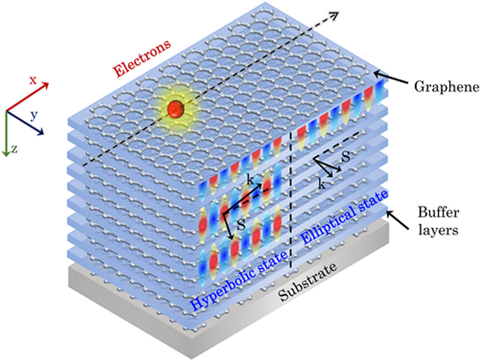
Fig. 1. CR excited by low-energy electrons in the GHM. Features of the hyperbolic CR in the hyperbolic state (left half) and conventional CR in the elliptical state (right half).
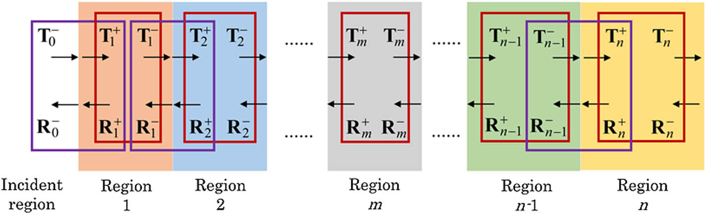
Fig. 2. Basic principles of SMT. T and R represent the transmission and reflection coefficients, respectively. The purple and red boxes indicate the connection of scattering matrices in the interface and inside the region, respectively.
Fig. 3. Effective in-plane permittivity of the GHM described by the EMT. Re ( ε eff - in ) E F = 0.15 eV d = 30 nm n eff v n E F = 0.15 eV d = 30 nm f t
Fig. 4. Effective CR properties. (a) Directions of wave vector k S E F = 0.15 eV d = 30 nm
Fig. 5. (a) Dispersion of plasmon modes in the GHM characterized by the imaginary part of reflection coefficient, Im ( r p ) log 100 Im ( r p )
Fig. 6. Electric field spatial distributions of excited plasmon modes parallel to the x 5 (a). (a) Point A with the optical mode at 45 THz. (b) Point B with the optical mode at 35 THz. (c) Point C with the second mode at 25 THz. (d) Point D with the fourth mode at 25 THz. (e) Point E with the fourth mode at 15 THz. (f) Point F with the tenth mode at 15 THz. The white dashed lines indicate graphene layers.
Fig. 7. Temperature-dependent photothermal properties. (a) Imaginary part of temperature-dependent conductivity, Im ( σ ) Re ( ε eff - in ) Re ( ε eff - in ) = 0 n eff u = 0.1 c n eff = 10 v n = 1 u = 0.1 c
Fig. 8. Nonlocal properties. (a) Imaginary part of nonlocal graphene conductivity, Im ( σ ) Re ( ε eff - in ) v F Im ( r p ) log 100 v F v b


Set citation alerts for the article
Please enter your email address

© Copyright 2018-2021 | Chinese Laser Press. All Rights Reserved 沪ICP备15018463号-20