
Zicheng Song, Pingping Min, Jiaqi Zhu, Lei Yang, Feng Han Lin. Wideband diffusion metabsorber for perfect scattering field reduction[J]. Photonics Research, 2022, 10(6): 1361
- Photonics Research
- Vol. 10, Issue 6, 1361 (2022)
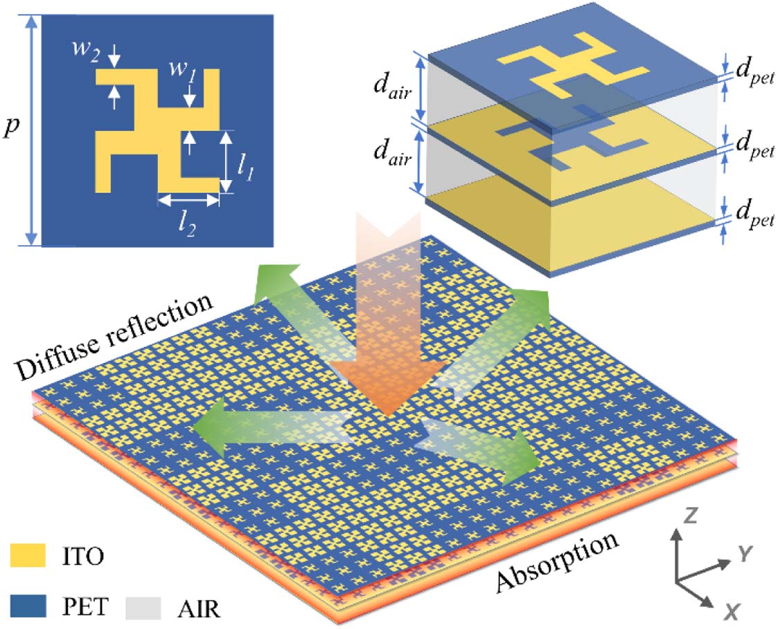
Fig. 1. Geometric structure of metabsorber element and schematic of wideband diffusion metabsorber under normal incidence.
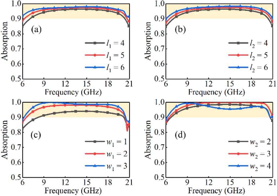
Fig. 2. Effect of changing structural parameters on absorption. (a) Length of gammadion-shaped resonator inner arm. (b) Length of gammadion-shaped resonator outer arm. (c) Width of gammadion-shaped resonator inner arm. (d) Width of gammadion-shaped resonator outer arm.
Fig. 3. Simulated (a) reflection amplitude and (b) reflection phase of optimized elements. The normalized input impedance of (c) elements 1 and (d) element 2. Insets shows thumbnails of elements.
Fig. 4. (a) Element distribution for optimized diffusion metabsorber. (b) Scattering field reduction results of calculation and simulation. (c) Ratio of absorption, diffusion, and reflection under normal incidence. (d) Averaged ratio of absorption, diffusion, and reflection from 8.5 to 20.3 GHz, and proportion of diffusion and reflection to the total scattered energy.
Fig. 5. (a)–(c) Calculated scattering patterns and full-wave simulated scattering field patterns for (d)–(f) optimized diffusion metabsorber and (g)–(i) PEC plate at frequencies of 10, 14, and 18 GHz.
Fig. 6. Simulated scattering field at (a)–(c) E -plane and (d)–(f) H -plane for diffusion metabsorber and PEC plate at frequencies of 10, 14, and 18 GHz.
Fig. 7. Simulated scattering field reduction of proposed diffusion metabsorber versus frequency and polarization angle (φ
Fig. 8. Simulated scattering field reduction of proposed diffusion metabsorber under oblique incidences of (a) TE and (b) TM polarization waves.
Fig. 9. (a) Photograph of the fabricated sample and normalized reflection spectra of the proposed sample at different incident angles: (b) 3° (normal incidence), (c) 20°, and (d) 40°. Inset in (b) shows the configuration of the arch method for reflection characterization.

Set citation alerts for the article
Please enter your email address
© Copyright 2018-2021 | Chinese Laser Press. All Rights Reserved 沪ICP备15018463号-20