1Electronic Materials Research Laboratory, Key Laboratory of the Ministry of Education & International Center for Dielectric Research, School of Electronic Science and Engineering, Faculty of Electronic and Information Engineering, Xi’an Jiaotong University, Xi’an 710049, China
2Max Planck Institute for the Science of Light, 91058 Erlangen, Germany
In this study, we theoretically proposed a method to achieve an electromagnetically induced transparency (EIT)-like effect in a whispering gallery mode resonator (WGMR) and experimentally validated the method in a lithium niobate (LN) device. Benefitting from the electro-optic and inverse piezoelectric effects of the LN material, two modes of the LN WGMR that are close in frequency can be tuned at different tuning rates, resulting in EIT-like resonance lineshapes. By varying the electric field applied to the LN WGMR, the full dynamic of the EIT-like phenomenon can be precisely controlled. The experimental results agreed well with the calculations based on the coupled mode theory. Moreover, we observed a hysteresis resulting from the photorefractive effect of LN. We believe our proposed method and demonstrated devices offer a way to control an EIT-like effect, which could have potential applications in light storage, quantum information processing, and enhanced sensing techniques.
1. INTRODUCTION
Electromagnetically induced transparency (EIT)-like effects are quantum interference effects that originate from different optical field transition pathways [1]. The EIT-like effect brings dramatic changes in the absorption and dispersion properties, which has potential applications including slow light [2], light storage [3], optical sensing [4], and quantum information processing [5]. EIT-like effects have been demonstrated in plasmonic metamaterials [6,7], photonic crystals [8], and whispering-gallery-mode resonators (WGMRs) [9–12]. In the last two decades, WGMRs have attracted a lot of interest for applications in fundamental physics and optical devices due to their high quality () factors [13,14], which makes them an ideal platform to realize EIT. To date, WGMR-based EIT-like effects have been realized in multimode waveguides [15], two directly coupled resonators [16,17], and a single resonator with two WGMs [18–21]. Usually, the formation of EIT in WGMRs is needed to satisfy: (1) the simultaneous excitation of two modes with different factors but adjacent resonance frequencies; and (2) the resonance frequency difference between the two modes, which can be tuned until coupling between the modes is observed. Recently, various methods have been used to tune the resonance frequencies and thereby realize the desired EIT-like lineshapes, such as coupling gap tuning [22–24], stretch tuning [9,10], and thermal tuning [19]. However, there are some challenges. In the case of stretch tuning, the required forces can disturb the coupled microcavity system. Thermal tuning requires complex design of a resonator with multilayer structures, which adds additional noise, for example, through thermal fluctuations and nonequilibrium points in the thermodynamic processes [25]. Furthermore, the stability of these systems is limited due to the fragile tapered fiber for the coupling. Apart from that, the materials used in these systems are mostly silicon dioxide. Silicon dioxide is a centrosymmetric crystal and does not have any significant electro-optical or piezoelectric properties. Thus, the resonance frequencies in silicon dioxide cannot be electrically tuned. In comparison, lithium niobate (LN) exhibits exceptional nonlinear optical, electro-optical, piezoelectric, and ferroelectric properties. Applying voltage to an LN WGM will change the resonance frequencies, which makes LN an excellent platform for electro-optical coupling applications. Until now, LN WGMRs have been successfully used in nonlinear optics [26] and microwave photonics [27]. Nevertheless, to the best of our knowledge, using the LN platform to regulate EIT-like effects has not yet been reported.
In this paper, we have proposed a scheme that uses the electro-optic and inverse piezoelectric effects of LN to induce and control an EIT-like effect in a single LN WGMR with a pair of copper electrodes on the surface. When applying an electrical field on the LN resonator, the frequency detuning of the two adjacent modes is flexibly controlled by changing the refractive index and the resonator size. Because different resonances exhibit different response rates to the applied electric field, we clearly observed EIT-like lineshapes in LN WGMR. The experimental results agree well with the corresponding coupled mode theory. Furthermore, the EIT was observed earlier when scanning the laser in the direction of decreasing wavelength than when increasing the wavelength. This hysteresis phenomenon is due to the photorefractive effect of LN, which makes the resonance wavelength shift to shorter wavelength direction [28].
2. THEORETICAL MODEL
A. Two Adjacent Resonance Modes Excited in a Single LN WGMR
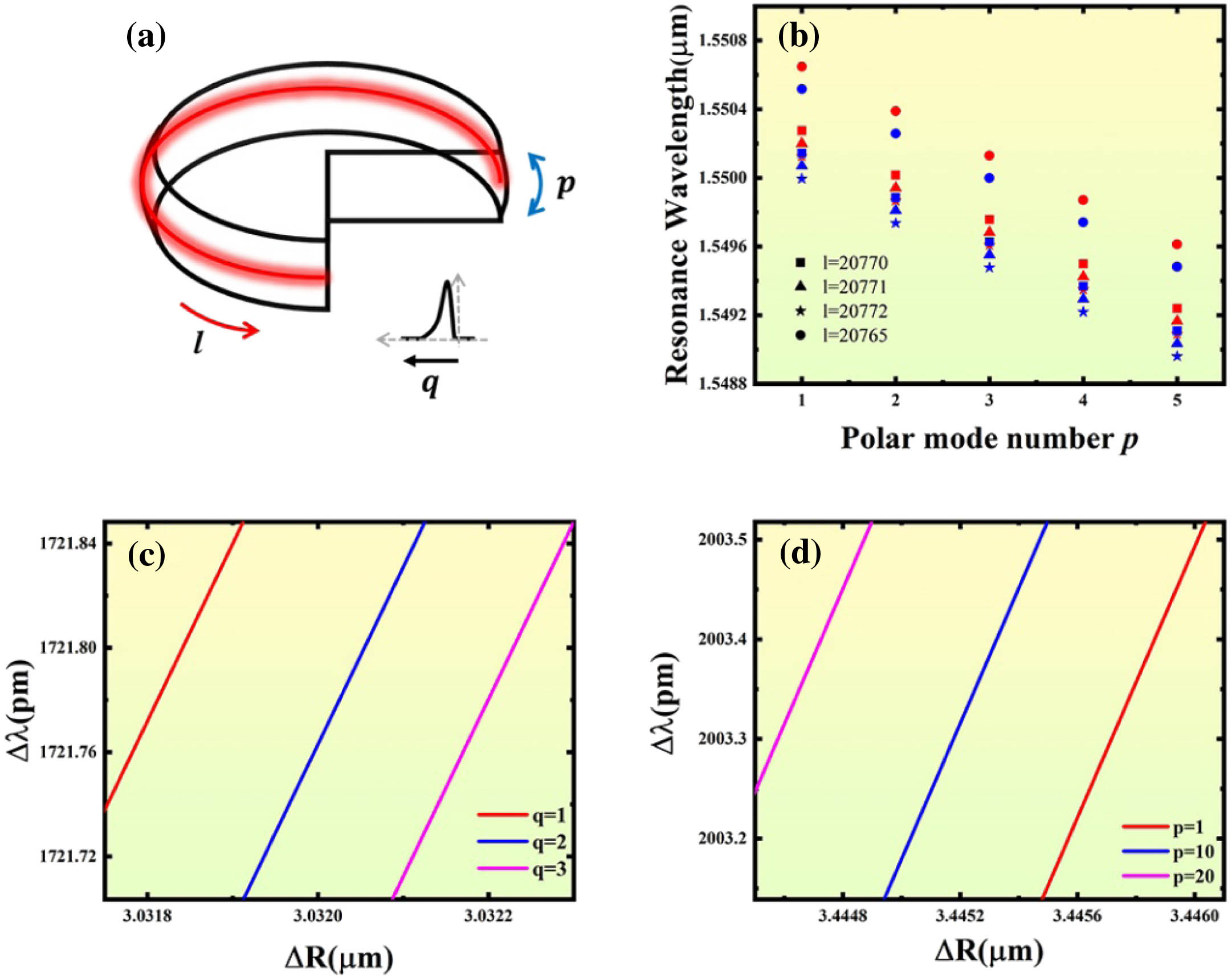
Here, we discuss the realization of an EIT-like effect in a single LN WGMR. To achieve the EIT, modes with close resonance frequencies must be excited and couple to each other. Due to resonator geometry, dispersion and fabrication defects, multiple mode families often exist in microresonators [14]. In a millimeter-scale WGMR, the resonance mode is characterized by radial mode number (), angular mode number (), and polar mode number (), which can be expressed in the form of (, , ), as shown in Fig. 1(a). Considering polarization effects, the resonance frequencies can be expressed as [29] where is the speed of light in vacuum, is the refractive index of the resonator, is the major radius of the WGMR, is the curvature of resonator, and is the th root of the Airy function. The parameter is 1 for TE modes and for TM modes. Figure 1(b) shows the resonance wavelengths as a function of polar mode numbers of a WGMR with and . It is seen that the resonance wavelength of the mode (1, 20,772, ) is localized between modes (2, 20,770, ) and (2, 20,771, ). This means that different radial mode families are intersecting or overlapping, which makes it possible to realize EIT in WGMRs.
Sign up for Photonics Research TOC. Get the latest issue of Photonics Research delivered right to you!Sign up now
Figure 1.(a) WGM schematic diagram. (b) Resonance wavelengths as a function of polar mode numbers in a single WGMR with and . The red and blue colors indicate and radial modes, respectively. Resonance wavelength as a function of the radius for (c) different radial modes with and and (d) different angular modes with and .
B. Resonance Wavelength Shifts of Different Order Modes with Different Radii
In a WGMR, the resonance wavelength () satisfies , where is the refractive index of the WGMR and is the radius of WGMR. The radius of the LN resonator can be changed by the piezoelectric effect. When the electric field is applied in the direction 3 (), the radius change from the inverse piezoelectric effect can be written as where is the piezoelectric coefficient matrix of LN. In our experiment, the radius is in the 1 direction, so we only considered the . The relationship between the resonance wavelength shifts of the different modes and the radius change is shown in Figs. 1(c) and 1(d). The shift of the resonance wavelengths is proportional to the radii of the different modes with different slopes. In Fig. 1(c), the slopes of , , and correspond to 0.68006 pm/nm, 0.68 pm/nm and 0.67995 pm/nm. In Fig. 1(d), the slopes of , , and correspond to 0.68007 pm/nm, 0.6802 pm/nm, and 0.68034 pm/nm. This suggests that two similar modes can be tuned at different frequency rates as the radius varies. When the frequency detuning of the two modes is sufficiently small, mode coupling will occur.
C. Resonance Wavelengths Shifts Induced by Refractive Index Changes
In the meantime, due to the electro-optic effect, the refractive index of LN will change when applying a voltage. When electric field is applied in the 3 direction (), the change of refractive index can be expressed as where is the electro-optic coefficient matrix of LN. The incident light is vertically polarized, so we only considered in our case. From Eq. (3), we know that . Because and , we know that . The change in refractive index leads to a change in the resonance wavelength and the change in the resonance wavelength is proportional to the applied voltage. Different WGMs have different sensitivities to electric fields, which makes the resonance wavelengths shift at different tuning rates. Thus, the frequency detuning of the two modes changes during this process, which leads to an EIT-like effect.
D. EIT Theory of a Single LN Resonator
Theoretically, an EIT-like effect can be understood as destructive interference between different optical pathways and can be explained by coupled mode equations [12,22,23]. As shown in Fig. 2, the dynamic equation of the two modes can be expressed as where and are the input and output laser fields; and represent the light fields of the modes A and B in the LN resonator; and are the resonance frequencies of the two WGMs; denotes the detuning of the probe laser frequency from the resonance frequency; , , are the coupling coefficients of mode A to waveguide, mode B to waveguide, and mode A to mode B coupling, respectively; is the cavity roundtrip time; is the intracavity decay rate and is the external cavity decay rate; and is the effective coupling strength between modes A and B.
Figure 2.Schematic illustration of a resonator with two WGMs.
We are interested in the steady-state regime of the system, corresponding to . The output field of the waveguide can be expressed as
The normalized transmission spectrum can be derived as where . We can see that only depends on the parameters , , , , , and . This suggests that EIT-like lineshapes can be engineered by modulating the coupling strength, intracavity decay rate, external cavity decay rate, and detuning between the two modes of the system.
E. Combined Influence of Two Effects on the Formation of EIT
In terms of the inverse piezoelectric effect, according to Section 2.2, when a forward voltage is applied, the negative sign of causes a decrease in and blue shift in the resonant wavelength. Conversely, when a reserve voltage is applied, increases and the resonant wavelength will be red shifted.
In terms of the electro-optic effect, according to Section 2.3, it can be observed that the forward voltage results in a decrease of , leading to a blue shift in the resonant wavelength. On the other hand, when the reverse voltage is applied, increases and, consequently, the resonant wavelength experiences a red shift.
To sum up, we find that the electro-optic effect and inverse piezoelectric effect cause a resonant wavelength shift in the same direction. Therefore, these two effects promote each other in the formation of EIT.
3. LN WGMR FABRICATION AND EXPERIMENTAL SETUP
A z-cut LN WGMR with a radius of 2.4 mm is fabricated by chemical mechanical polishing. The fabrication process can be found in our recent work [30]. A couple of copper electrodes are connected to the LN WGMR surface, as shown in Fig. 3(a).
Figure 3.(a) LN WGMR with copper electrodes. (b) Schematic of the experimental setup. An LN WGMR is coupled to a rutile prism. HWP, half-wave plate; and PD, photodetector.
The experimental setup is schematically depicted in Fig. 3(b). A tunable, narrow linewidth () laser at the C-band wavelength is used to measure the transmission spectrum of the LN resonator. A half-wave plate (HWP) and Glan–Taylor prism are used to control the polarization of the input light. The LN resonator is mounted on a 3D translation stage with a resolution of 20 nm to precisely control the coupling. The laser light is evanescently coupled into the LN resonator via a rutile prism with . A direct current voltage source is used to control the voltage applied to the LN resonator. The transmitted light is detected by a 12 MHz bandwidth photodetector and recorded by a digital oscilloscope.
4. EXPERIMENTAL RESULTS AND ANALYSIS
To effectively excite different modes, the coupling region of the prism maintains physical contact with the LN WGMR surface. In the experiment, we used a triangular wave from function generator to control the laser frequency. Figures 4(a)–4(e) describe how the transmission spectrum varies with an increase in the voltage and the left part corresponds to an increase in wavelength, while the right part corresponds to a decrease in the wavelength. Interestingly, we find that the resonance frequencies of WGMs are asymmetric in different laser scan directions, which is a result of the photorefractive effect [28]. The photorefractive effect is caused by optical excitation of the charge carriers from LN defects. These carriers migrate and create electric fields that shift the optical resonance frequencies through the electro-optic effect [31]. Figure 4(f) shows the transmission spectrum of the two modes with the EIT-like effect. The two modes have different optical qualities: one has a lower (mode 1, ) and the other has a higher (mode 2, ). They have similar resonance frequencies but different mode numbers. Figure 4(g) illustrates the relationship between the voltage and resonance wavelength shift of modes 1 and 2. We can see that the resonance detuning between the two modes is proportional to the applied voltage. The detuning rate of mode 1 is , which is faster than that of mode 2 with . This makes it possible to observe EIT-like lineshapes. Figures 4(a)–4(e) show the formation and control of the EIT-like effect in an LN resonator. Initially, the resonance frequencies between mode 1 and mode 2 are far away from each other, and mode 2 is at a higher frequency. There are no coupling effects and their resonance dips are Lorentz-like, as shown in Fig. 4(a). By changing the voltage, both modes shift toward the shorter wavelength direction, but at different detuning rates, leading to a decreasing frequency detuning between mode 1 and mode 2. Eventually, the two modes begin to interact and Fano-like lineshapes are formed, as shown in Figs. 4(b) and 4(c). In the decreasing wavelength direction, the frequency detuning between the two modes becomes zero when the voltage is increased up to 120 V. Then, a “transparent” window can be found and an EIT-like lineshape is formed, as shown in Fig. 4(d). As the voltage further increases, the two modes cross each other and mode 1 has a higher frequency. The EIT-like lineshapes turn into Fano-like lineshapes, as illustrated in Fig. 4(e). Finally, if the voltage increases further, the Fano-like lineshapes will become two separate Lorentz curves. More importantly, we found a hysteresis in this process. When we compared the lineshapes in the dashed black ellipses in Figs. 4(d) and 4(e), the EIT-like effect was formed faster when the wavelength decreases. Because of the photorefractive effect, when the wavelength decreases, the resonance peaks are broadened and shifted to the blue side, so the frequency detuning between the two resonance modes decreases and they start to interact earlier. When the wavelength increases, the resonance linewidth decreases and blue shifts while the frequency detuning between the two resonance modes increases and the interaction occurs later.
Figure 4.(a)–(e) Normalized experimental transmission spectrum changes with increasing voltage. The pink arrow indicates mode 1, while the blue arrow indicates mode 2. (f) Zoom-in for the normalized transmission of adjacent modes 1 and 2, corresponding to the green box in Fig. 3(a). (g) Resonance wavelength shifts of two modes as a function of the applied voltage.
To better understand the observed EIT-like effect, we used Eq. (7) to fit the experimental data, as shown in Fig. 5; Figs. 5(a)–5(e) are measured curves, and Figs. 5(f)–5(j) are fitted curves. The experimental spectra are in excellent agreement with the theoretical results. Small discrepancies between the theoretical and experimental results may be ascribed to the thermal effect when scanning the laser wavelength and the weak coupling with other low- modes. From the theoretical calculations, the frequency detuning is calculated as , which indicates that the two modes have changed positions during the formation of the EIT-like lineshapes. In addition, the coupling condition for each mode changes slightly with an increase in the voltage, but mode A is always in the overcoupled regime because of , while mode B always remains in the undercoupled regime because of . This could be due to the physical contact between the resonator and the prism.
Figure 5.(a)–(e) Experimental data for the normalized transmission spectra of the LN WGM coupled via a rutile prism at different voltages. From the top panel to the bottom panel, the voltage changes from 0 V to 160 V, at intervals of 40 V. (f), (g) Theoretical calculation of the spectrum of the coupled system. The theoretical parameters are: , , , , and .
In summary, we theoretically proposed what we believe, to the best of our knowledge, is a novel method to control an EIT-like effect in a single WGMR and experimentally observed it in an LN WGMR. Due to the electro-optic and inverse piezoelectric effects of LN, different WGMs show different sensitivities to electric fields. By varying the voltage applied to the LN WGMR, the resonance frequencies can be controlled, and we observed the EIT-like phenomenon at different resonance detunings. In addition, because of the photorefractive effect, a hysteresis of the lineshape was observed, which depends on the laser scan direction. This discovery is of great significance for our future research into the low-frequency electro-optic response of LN. Our proposed voltage tuning mechanism provides an efficient, easy way to control mode coupling and transmission spectra, which allows this scheme to be further used in all-optical switches and quantum information processing.