
Kai Qu, Ke Chen, Qi Hu, Junming Zhao, Tian Jiang, Yijun Feng. Deep-learning-assisted inverse design of dual-spin/frequency metasurface for quad-channel off-axis vortices multiplexing[J]. Advanced Photonics Nexus, 2023, 2(1): 016010
- Advanced Photonics Nexus
- Vol. 2, Issue 1, 016010 (2023)
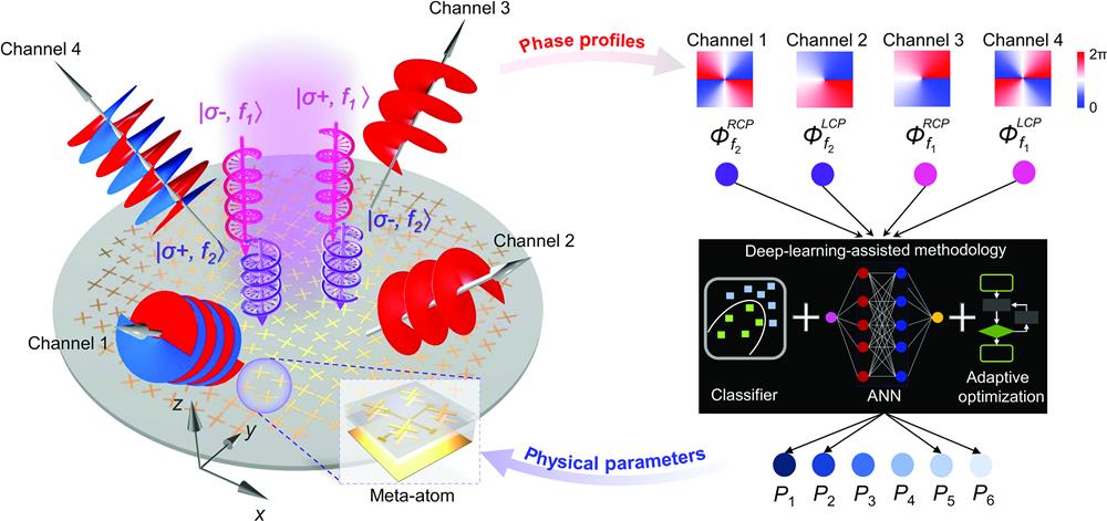
Fig. 1. Conceptual schematic of the dual-spin/frequency multiplexing metasurface for spin-to-OAM conversion and its inverse design approach. Light with opposite spin states and different frequencies converted to optic vortex carrying arbitrary OAM mode after being reflected from the metasurface. The inset shows the spiral phase distribution of the four VBs with topological charges
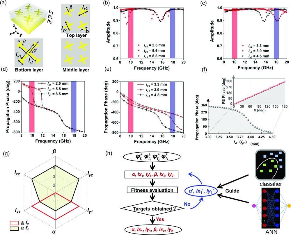
Fig. 2. EM response of the meta-atom and realization of the inverse design. (a) Schematic of the meta-atom with multilayer configuration. The geometric parameters of the top layer and middle one are the same. When rotation angles of all the cross resonators remain 0 deg, the simulated linearly copolarized amplitude under
Fig. 3. Realization of dual-frequency spin-to-orbit metaconverter. (a) Physical parameter distributions of the elements in sample 1. (b) Calculated phase distribution for RCP channel at 9.8 GHz, LCP channel at 9.8 GHz, RCP channel at 17.8 GHz, and LCP channel at 17.8 GHz. (c) Photograph of the fabricated spin-to-orbit metaconverter. (d) Normalized simulated power patterns in momentum space. (e) Simulated and measured intensity patterns and phase patterns of different OAM beams in the four channels.
Fig. 4. Realization of dual-frequency VVB metamultiplexer. (a) Parameter distributions of the elements in sample 2. (b) Calculated phase distributions for RCP channel at 9.8 GHz, LCP channel at 9.8 GHz, RCP channel at 17.8 GHz, and LCP channel at 17.8 GHz. (c) Photograph of the fabricated VVB meta-multiplexer. (d) Normalized simulated power patterns and their positions on the three HOPSs. Beam #1 is designed at 9.8 GHz and beams #2 and #3 are designed at 17.8 GHz. (e) Simulated and measured intensity patterns of two orthogonal LP components. The white arrows indicate the detected polarization direction.

Set citation alerts for the article
Please enter your email address
© Copyright 2018-2021 | Chinese Laser Press. All Rights Reserved 沪ICP备15018463号-20