• Opto-Electronic Advances
  • Vol. 2, Issue 6, 190001 (2019)
Pei Hang He1, Hao Chi Zhang2, Xinxin Gao1, Ling Yun1, Wen Xuan Tang1, Jiayuan Lu1, Le Peng Zhang1, and Tie Jun Cui1、*
Author Affiliations
  • 1State Key Laboratory of Millimeter Waves, Southeast University, Nanjing 210096, China
  • 2School of Electrical and Electronic Engineering, Nanyang Technological University, Nanyang Avenue, 639798, Singapore
  • show less
    DOI: 10.29026/oea.2019.190001 Cite this Article
    Pei Hang He, Hao Chi Zhang, Xinxin Gao, Ling Yun, Wen Xuan Tang, Jiayuan Lu, Le Peng Zhang, Tie Jun Cui. A novel spoof surface plasmon polariton structure to reach ultra-strong field confinements[J]. Opto-Electronic Advances, 2019, 2(6): 190001 Copy Citation Text show less
    (a) The new spoof SPP TL with zigzag grooves, in which the width of the TL is w1, the period of the TL is p1, the width of the grooves is a1 and the depth of the grooves is d1, the folding extent parameters are X and Y. (b) The conventional spoof SPP TL with straight grooves, in which the width of the TL is w2, the period of the TL is p2, the width of the grooves is a2, the vertical depth of the grooves is d2.
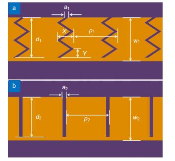
    Fig. 1. (a) The new spoof SPP TL with zigzag grooves, in which the width of the TL is w1, the period of the TL is p1, the width of the grooves is a1 and the depth of the grooves is d1, the folding extent parameters are X and Y. (b) The conventional spoof SPP TL with straight grooves, in which the width of the TL is w2, the period of the TL is p2, the width of the grooves is a2, the vertical depth of the grooves is d2.
    (a) Dispersion diagrams of the new spoof SPP TLs with different X, where Y is set as 1 mm. (b) Dispersion diagrams of the new spoof SPP TLs with different Y, where X is set as 1 mm. (c) Dispersion diagrams of the conventional spoof SPP TLs with different d2. (d) The plot of the relationship between depth of straight grooves and cutoff frequency.
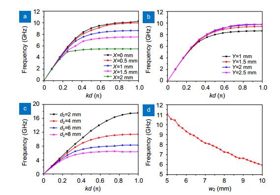
    Fig. 2. (a) Dispersion diagrams of the new spoof SPP TLs with different X, where Y is set as 1 mm. (b) Dispersion diagrams of the new spoof SPP TLs with different Y, where X is set as 1 mm. (c) Dispersion diagrams of the conventional spoof SPP TLs with different d2. (d) The plot of the relationship between depth of straight grooves and cutoff frequency.
    [in Chinese]
    Fig. 3. [in Chinese]
    The simulated (a) S21 and (b) S11 of the whole structures with different X, in which Y is fixed as 1 mm. From (a) and (b), it can be concluded that larger X implies larger equivalent depth. The simulated (c) S12 and (d) S11 of the whole structures with different Y, in which X is fixed as 1 mm. From (c) and (d), it can be concluded that larger Y implies smaller equivalent depth.
    Fig. 4. The simulated (a) S21 and (b) S11 of the whole structures with different X, in which Y is fixed as 1 mm. From (a) and (b), it can be concluded that larger X implies larger equivalent depth. The simulated (c) S12 and (d) S11 of the whole structures with different Y, in which X is fixed as 1 mm. From (c) and (d), it can be concluded that larger Y implies smaller equivalent depth.
    [in Chinese]
    Fig. 5. [in Chinese]
    The two plots of field distribution are normalized on the same dimension. (a) The simulated amplitude distributions of electric field near the conventional spoof SPP TL with straight grooves where w2=5 mm, d2=4.6 mm, p2=5 mm and a2=0.4 mm. (b) The simulated amplitude distributions of electric field near the new spoof SPP TL with zigzag grooves where w1=5 mm, d1=4.6 mm, p1=5 mm, a1=0.4 mm, X=1.5 mm and Y=1 mm. From this figure, strong field confinement of the new spoof SPP TL with undulant grooves can be observed.
    Fig. 6. The two plots of field distribution are normalized on the same dimension. (a) The simulated amplitude distributions of electric field near the conventional spoof SPP TL with straight grooves where w2=5 mm, d2=4.6 mm, p2=5 mm and a2=0.4 mm. (b) The simulated amplitude distributions of electric field near the new spoof SPP TL with zigzag grooves where w1=5 mm, d1=4.6 mm, p1=5 mm, a1=0.4 mm, X=1.5 mm and Y=1 mm. From this figure, strong field confinement of the new spoof SPP TL with undulant grooves can be observed.
    (a) The sample of the typical spoof SPP TL with straight grooves, in which t1=0.508 mm, w1=5 mm, a1=0.4 mm, p1=5 mm and d=4.6 mm.(b) The sample of the new spoof SPPs TL with undulant grooves, in which t2=0.508 mm, w2=5 mm, a2=0.4 mm, p2=5 mm, X=1.5 mm and Y=1 mm.
    Fig. 7. (a) The sample of the typical spoof SPP TL with straight grooves, in which t1=0.508 mm, w1=5 mm, a1=0.4 mm, p1=5 mm and d=4.6 mm. (b) The sample of the new spoof SPPs TL with undulant grooves, in which t2=0.508 mm, w2=5 mm, a2=0.4 mm, p2=5 mm, X=1.5 mm and Y=1 mm.
    [in Chinese]
    Fig. 8. [in Chinese]
    [in Chinese]
    Fig. 9. [in Chinese]
    [in Chinese]
    Fig. 10. [in Chinese]
    XYGeometrically equivalent depthSimulated equivalent depth
    0/4.64.6
    0.515.15.0
    116.56.0
    1.518.36.7
    2110.38.3
    11.55.55.6
    125.15.2
    12.55.05.1
    Table 1. Geometrical equivalent depths and simulated equivalent depths of zigzag grooves (unit: mm)]]>
    Pei Hang He, Hao Chi Zhang, Xinxin Gao, Ling Yun, Wen Xuan Tang, Jiayuan Lu, Le Peng Zhang, Tie Jun Cui. A novel spoof surface plasmon polariton structure to reach ultra-strong field confinements[J]. Opto-Electronic Advances, 2019, 2(6): 190001
    Download Citation