Abstract
Ultrathin corrugated metallic structures have been proved to support spoof surface plasmon polariton (SPP) modes on two-dimension (2D) planar microwave circuits. However, to provide stronger field confinement, larger width of strip is required to load deeper grooves, which is cumbersome in modern large-scale integrated circuits and chips. In this work, a new spoof SPP transmission line (TL) with zigzag grooves is proposed. This new structure can achieve stronger field confinement compared to conventional one with the same strip width. In other words, the proposed spoof SPP TL behaves equivalently to a conventional one with much larger size. Dispersion analysis theoretically indicates the negative correlation between the ability of field confinement and cutoff frequencies of spoof SPP TLs. Numerical simulations indicate that the cutoff frequency of the proposed TL is lower than the conventional one and can be easily modified with the fixed size. Furthermore, two samples of the new and conventional spoof SPP TLs are fabricated for experimental demonstration. Measured S-parameters and field distributions verify the ultra-strong ability of field confinement of the proposed spoof SPP TL. Hence, this novel spoof SPP structure with ultra-strong field confinement may find wide applications in microwave and terahertz engineering. Introduction
Surface plasmon polaritons (SPPs) are a kind of special electromagnetic (EM) wave modes which exist on the interface between two media with opposite permittivities. Although medium with negative permittivity is peculiar, it can be realized based on the plasmonic behavior of metal at visible or ultraviolet (UV) frequencies1. Hence, SPPs can propagate along the interface between metals and common dielectric (e.g., air) but decay exponentially in the vertical directions according to the Maxwell's equations. SPPs exhibit excellent properties of field confinement and have intrigued great research interests in the past decades. SPPs are potential to be applied in many areas, for instance, the super-resolution imaging2, 3, miniaturized sensors1, 4, and photovoltaics5.
Nevertheless, inherent ohmic loss of metal at optical frequencies is very high so that SPP modes attenuate rapidly. Hence, further development of plasmonic devices is limited. To avoid the enormous transmission attenuation, one of the potential strategies is to realize SPP-based devices at lower frequencies (e.g. terahertz and microwave frequencies), which is supposed to alleviate the ohmic loss effectively.
The major difficulty to realize SPP-based devices in lower band is that metals approximately behave as perfectly electric conductors (PECs) rather than plasmonic materials with negative permittivity, and thus, natural SPPs cannot be excited. To mimic natural SPPs at terahertz and microwave frequencies, the concept of plasmonic metamaterials, which can support the SPP-like EM waves named as spoof (or designer) SPPs, is proposed6-22. Plasmonic metamaterials can be constructed by metallic surface with special subwavelength decorations, such as one-dimensional arrays of grooves23 or two-dimensional arrays of pits and hills6, 24. Recently, a kind of ultrathin plasmonic transmission line (TL) composed of corrugated metallic strip which can be easily fabricated by printed circuit board (PCB) technology is reported25. Microwave and terahertz EM waves on this TL can be manipulated by adjusting geometrical parameters of the metallic structure. Based on the ultrathin corrugated structure, many developed spoof SPP TLs26-32 have been proposed to construct various SPP-based devices and shown many advantages like low dielectric loss33, minimized packaging27 and crosstalk suppression34.
Despite of the difference between these spoof SPP TLs, the depth of grooves, as shown in Fig. 1(a), is always the key geometrical parameter to control the dispersion property of spoof SPP TLs. To achieve stronger field confinement of spoof SPPs, deeper grooves are required and greater strip width is necessary. In other words, there is a contradiction between strong field confinement and miniaturization of geometrical size for spoof SPP TLs, which could be a crucial limitation in real applications.

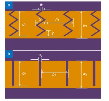
Figure 1.(a) The new spoof SPP TL with zigzag grooves, in which the width of the TL is w1, the period of the TL is p1, the width of the grooves is a1 and the depth of the grooves is d1, the folding extent parameters are X and Y. (b) The conventional spoof SPP TL with straight grooves, in which the width of the TL is w2, the period of the TL is p2, the width of the grooves is a2, the vertical depth of the grooves is d2.
In this paper, a new spoof SPP TL with zigzag grooves is proposed. Meanwhile, a conversion section to transit the EM mode of traditional coplanar waveguide (CPW) into that of the proposed spoof SPP TL is designed. Zigzag grooves can be regarded as the folded form of straight grooves, which makes it possible to provide stronger field confinement with a limited strip width. Dispersion theoretical analysis indicates the stronger confinement ability of this new TL compared to conventional one. Two samples are fabricated to provide experimental demonstration of this design and analysis. Measured S-parameters and electric field distributions indicate the enhanced field confinement ability due to the zigzag grooves. The ultra-strong field confinement of the spoof SPP TL with zigzag grooves can be utilied to suppress the crosstalk between channels26 by concentrating the fields more tightly around the spoof SPP TLs. Moreover, the proposed structure can reduce the area of some microwave devices including filters and couplers where the electrical lengths of microstrips are very large. Hence, the proposed spoof SPP TL with ultra-strong field confinement opens up an avenue to achieve minimized spoof SPP-based devices and circuits.
Results and discussion
A new spoof SPP TL with zigzag grooves is proposed. Figs. 1(a) and 1(b) exhibit the unit configurations of the new and conventional spoof SPP TL, respectively. The material of the substrate is Rogers RT5880 with the relative permittivity εr =2.2, the loss tangent tanδ=0.0009 and the thickness of 0.508 mm. For the structure in Fig. 1(a), the width of the TL is w1, the vertical depth of the grooves is d1, the period of the TL is p1, and the width of the grooves is a1. The folding extent of zigzag grooves can be described by the geometrical parameters X and Y in Fig. 1(a). When a1 is small, the geometrical equivalent depth of grooves, denoted by dg, can be expressed as
For the conventional structure in Fig. 1(b), the width of the TL is w2, the depth of the grooves is d2, the period of the TL is p2, and the width of the grooves is a2.
To analyze the dispersion property of the proposed spoof SPP TL, the Eigen-mode simulation of the commercial software, CST Microwave Studio, is used. Periodic units with different X and Y are simulated, where the other parameters are fixed as w1=5 mm, d1=4.6 mm, p1=5 mm and a1=0.4 mm, and the results are shown in Figs. 2(a) and 2(b). Note that Y is set as 1 mm in Fig. 2(a) and X is set as 1 mm in Fig. 2(b). As the comparison, dispersion curves of spoof SPP TL units in Fig. 1(b) with different depths of the grooves d2 and fixed (w2-d2)=0.4 mm are also analyzed, as shown in Fig. 2(c), where a2 is equal to 0.4 mm and p2 is equal to 5 mm. In Fig. 2(c), it can be observed that the larger the depth of grooves is, the more the dispersion curves deviate from the light line, which leads to a lower cutoff frequency. All the dispersion curves in Figs. 2(a)-2(c) deviate from the linear track gradually and approaches respective cutoff frequencies with the increase of frequency, which is the typical property of natural SPPs. According to equation (1) and Fig. 2(c), the larger X is (or the smaller Y is), the larger dg is, which will lead to a stronger field confinement. The simulated results of dispersion curves verify this prediction, because the cutoff frequency is decreasing with the increase of dg.
Figure 2.(a) Dispersion diagrams of the new spoof SPP TLs with different X, where Y is set as 1 mm. (b) Dispersion diagrams of the new spoof SPP TLs with different Y, where X is set as 1 mm. (c) Dispersion diagrams of the conventional spoof SPP TLs with different d2. (d) The plot of the relationship between depth of straight grooves and cutoff frequency.
Next, the negative correlation between the ability of field confinement and cutoff frequency will be demonstrated. Based on the dispersion equations, the evanescent factor of SPP modes in the air region αa and the wavenumber kp along the propagation direction satisfy
where k0 is the wavenumber in vacuum, εa and μa are the relative permittivity and permeability of air, respectively. Similarly, the evanescent factor in the dielectric (substrate) region αd and the wavenumber kp along the propagation direction satisfy
where εd and μd are the relative permittivity and permeability of the dielectric. It can be observed that larger wavenumber leads to larger evanescent factor, which indicates stronger field confinement. According to the above dispersion analysis of spoof SPPs, there is a negative correlation between the ability of field confinement and cutoff frequencies as well. Hence, cutoff frequency can be regarded as an index of field confinement ability. The plot of the relationship between depth of straight grooves and cutoff frequency is shown in Fig. 2(d). Based on Fig. 2(d), the simulated equivalent depth of zigzag grooves, ds, can be defined as the depth of straight grooves which can provide the same cutoff frequencies. Table 1 exhibits the geometrical equivalent depths and simulated equivalent depths of zigzag grooves with different X and Y. It can be observed that the dg and ds are almost identical when the folding extent of zigzag grooves is slight. The reason why the difference between dg and ds enhances is that the coupling between adjacent zigzag gaps becomes stronger when the folding extent of zigzag grooves increases. Even so, it is possible to realize stronger field confinement on a much narrower metallic TL by utilizing zigzag grooves compared to straight grooves. When the period and width of the structure are fixed, the proposed structure provides two degrees of freedom (X and Y) to manipulate the field confinement. Oblique grooves can also provide an enhanced field confinement, but the oblique angle cannot be too large because there will be many difficulties in the designing of devices and circuits if the groove exceeds the period of the TL.
| X | Y | Geometrically equivalent depth | Simulated equivalent depth |
| 0 | / | 4.6 | 4.6 |
| 0.5 | 1 | 5.1 | 5.0 |
| 1 | 1 | 6.5 | 6.0 |
| 1.5 | 1 | 8.3 | 6.7 |
| 2 | 1 | 10.3 | 8.3 |
| 1 | 1.5 | 5.5 | 5.6 |
| 1 | 2 | 5.1 | 5.2 |
| 1 | 2.5 | 5.0 | 5.1 |
Table 1. Geometrical equivalent depths and simulated equivalent depths of zigzag grooves (unit: mm)]]>
Since the impedance and wavenumber of the proposed spoof SPP TL do not match those of traditional microwave TLs such as microstrip and CPW, the spoof SPPs cannot be excited directly. In order to feed the proposed spoof SPP TL from CPW, a conversion structure constructed by tapered strip, gradient zigzag grooves and flaring ground is designed35, 36, as shown in Fig. 3. This conversion structure can realize the smooth matching of impedance and wavenumber between CPW and the proposed spoof SPP TL in a wide band. The substrate is Rogers RT 5880 with the relative permittivity εr=2.2, the loss tangent tanδ=0.0009 and the thickness of 0.508 mm. The impedance of the feeding CPW is designed as 50 Ω to match standard subminiature version A (SMA) connectors, where the width of the centre strip and the gaps of the CPW are 3 mm and 0.15 mm, respectively. For the spoof SPP TL, the width w1 is 5 mm, the period p1 is 5 mm, the width of the grooves a1 is 0.4 mm. The vertical depth of the zigzag grooves d1 is fixed as 4.6 mm while X and Y is variable to mimic different equivalent depths of grooves. The size of the whole board is 150 mm×50 mm.
Figure 3.
Figure 4 exhibits simulated S-parameters of the whole structure with different X and Y using the CST Microwave Studio. From the results in Fig. 4(a) where Y is fixed as 1 mm, it can be observed that the transmission coefficient (S21) is better than -2.5 dB and the cutoff frequency decreases obviously as X increases. Note that the S21 worsens little when X becomes larger, which means that the transmission efficiency does not decrease obviously with the increase of X. Note that when X=0, this structure is identical to conventional spoof SPP TL with straight grooves and its cutoff frequency is the highest. In other words, the field confinement of conventional spoof SPP TL with straight grooves is the weakest. Figure 4(c) shows the simulated S-parameters for different Y but constant X (1 mm). The cutoff frequency decreases obviously as Y increases and the transmission efficiency is kept as well, and the cutoff frequency increases obviously as Y increases. Hence, it can be concluded that the transmission efficiency of the conversion structure does not decrease obviously with the increase of folding extent of zigzag grooves. The insertion loss of these structures is caused by the conversion structure with flaring ground. To demonstrate the low transmission loss of the spoof SPP TL with zigzag grooves, two samples with the same conversion sections but different lengths (10 mm and 100 mm) of spoof SPP TL are simulated, as shown in Fig. 5. It can be observed that even though the length of spoof SPP TL is 10 times larger, negligible increase of insertion loss can be found, which implies the low-loss property of the proposed spoof SPP TL. The numerical simulated results in Fig. 4 imply that the structure with zigzag grooves provides lower cutoff frequency than straight grooves, which is the demonstration of stronger field confinement as analyzed above. Meanwhile, the confinement ability can be easily tuned by modifying the folding extent of zigzag grooves.
Figure 4.The simulated (a) S21 and (b) S11 of the whole structures with different X, in which Y is fixed as 1 mm. From (a) and (b), it can be concluded that larger X implies larger equivalent depth. The simulated (c) S12 and (d) S11 of the whole structures with different Y, in which X is fixed as 1 mm. From (c) and (d), it can be concluded that larger Y implies smaller equivalent depth.
Another method to observe the enhanced field confinement due to the zigzag grooves is to analyze the simulated amplitude distribution of electric field on the cross sections of these two kinds of spoof SPP TLs, as shown in Fig. 5.
Figure 5.
The geometrical parameters of the conventional spoof SPP TL with straight grooves in Fig. 6(a) are set as w2=5 mm, d2=4.6 mm, p2=5 mm and a2=0.4 mm, while the proposed spoof SPP TL with zigzag grooves in Fig. 6(b) are set as w1=5 mm, d1=4.6 mm, p1=5 mm, a1=0.4 mm, X=1.5 mm and Y=1 mm. These two plots of field distribution are normalized on the same dimension. It can be observed that the field is confined tighter near the spoof SPP TL with zigzag grooves than the one with straight grooves at 6 GHz, which indicates tighter convergence of energy. In other words, stronger field confinement can be observed in Fig. 6.
Figure 6.The two plots of field distribution are normalized on the same dimension. (a) The simulated amplitude distributions of electric field near the conventional spoof SPP TL with straight grooves where w2=5 mm, d2=4.6 mm, p2=5 mm and a2=0.4 mm. (b) The simulated amplitude distributions of electric field near the new spoof SPP TL with zigzag grooves where w1=5 mm, d1=4.6 mm, p1=5 mm, a1=0.4 mm, X=1.5 mm and Y=1 mm. From this figure, strong field confinement of the new spoof SPP TL with undulant grooves can be observed.
To verify above analysis of the proposed structure, two samples, a conventional spoof SPP TL with straight grooves and a new spoof SPP TL with zigzag grooves, are fabricated, as shown in Fig. 7. The substrate and all the geometrical parameters of the two samples are identical to those of the models in the previous simulations. For the new spoof SPP TL, the folding parameters of zigzag grooves are set as X=1.5 mm and Y=1 mm. In the experiment, the vector network analyzer (VNA) AV3672B is used to obtain the transmission coefficient of these two samples. To connect the samples to the VNA, standard SMA connectors are welded onto all the ports of these two samples. Measured S-parameters of these two samples are shown in Fig. 8. It can be easily observed that the -10 dB cutoff frequency of the new spoof SPP TL (8.0 GHz) is much lower than that of the conventional one (10.1 GHz), implying stronger ability of field confinement. The disparity between the simulation and measurement is caused by the welding of SMA connectors and fabrication errors. Although the relative error of welding of SMA connectors impacts the impedance matching of CPW ports dramatically, it can be avoided by industrial-grade welding technology.
Figure 7.(a) The sample of the typical spoof SPP TL with straight grooves, in which t1=0.508 mm, w1=5 mm, a1=0.4 mm, p1=5 mm and d=4.6 mm.
(b) The sample of the new spoof SPPs TL with undulant grooves, in which t2=0.508 mm, w2=5 mm, a2=0.4 mm, p2=5 mm, X=1.5 mm and Y=1 mm.
Figure 8.
In addition, near-field distributions of z-component of electric field of the samples at 6 GHz and 8 GHz are also measured based on a electromagnetic measurement system, composed of a electromagnetic shielding chamber, a VNA and a monopole antenna (as a probe) installed in a mechanical platform, as shown in Fig. 9. In each experiment, one port of the sample is connected with the 50 Ω matching impedance and the other port of the sample is connected with port 1 of the VNA through a coaxial cable. The monopole antenna (probe) on the mechanical platform is connected with port 2 of the VNA through another coaxial cable. The measured plane is at 1 mm above the surface of these two samples. Simulated and measured near-field distributions of electric field on the same plane of the samples at 6 GHz and 8 GHz are shown in Fig. 10. SPP-like modes are found on both the conventional and proposed spoof SPP structures, where the transmission wavelength at 6 GHz of the sample with zigzag grooves is smaller than that of the conventional one with straight grooves. Meanwhile, it can be observed that the electric field is confined tighter near the spoof SPP TL with zigzag grooves than the conventional one at 6 GHz. And thus, more energy will be concentrated near the metallic strip with zigzag grooves compared to the other one. At 8 GHz, the sample with straight grooves works while the one with zigzag grooves is at the cutoff state, which indicates the difference in cutoff frequency and field confinement ability as well. All the measured results mentioned above experimentally demonstrate that the dispersion curve of the proposed spoof SPP structure locates beneath the conventional case and the field confinement ability is virtually enhanced due to the zigzag grooves.
Figure 9.
Figure 10.
Conclusions
In this paper, a new spoof SPP TL with zigzag grooves is proposed, which can provide much stronger field confinement than the conventional one with straight grooves. The zigzag grooves can be considered as folded straight grooves or much deeper straight grooves with the same strip width. Dispersion analysis of the proposed structure indicates the stronger field confinement from the view of theory. Simulated and measured S-parameters prove that the field confinement ability of the spoof SPP structure can be easily modified by simply changing the geometrical parameters of the zigzag grooves with the fixed strip width. Geometrical and simulated equivalent depths of zigzag grooves are provided to estimate the field confinement of the proposed structure. Simulated and measured near-field distributions of electric fields visibly demonstrate that the propagating energy is concentrated much more tightly near the spoof SPP structure with zigzag grooves compared to the other case. In one word, controllable and outstanding field confinement ability of the new spoof SPP structure with a compact size is verified. Hence, this structure may find wide applications in microwave and terahertz engineering in the future.
Acknowledgements
We are grateful for financial supports from the National Natural Science Foundation of China under Grant Nos. 61871127, 61701246, 61631007, 61571117, 61501112, 61501117, 61522106, 61722106, 61701107, and 61701108, and 111 Project under Grant No.111-2-05.
Author contributions
P. H. H. proposed the original idea and supervised the project. H. C. Z. and X. X. G. fabricated the samples and performed the measurements. L. Y. N., W. X. T., J. Y. L. and L. P. Z. improved the writing of the paper. T. J. C. supervised the whole project.
Competing interests
The authors declare no competing financial interests.
References
[1] W L Barnes, A Dereux, T W Ebbesen. Surface plasmon subwavelength optics. Nature, 424, 824-830(2003).
[2] A C Jones, R L Olmon, S E Skrabalak, B J Wiley, Y N Xia et al. Mid-IR plasmonics: near-field imaging of coherent plasmon modes of silver nanowires. Nano Lett, 9, 2553-2558(2009).
[3] N Fang, H Lee, C Sun, X Zhang. Sub-diffraction-limited optical imaging with a silver superlens. Science, 308, 534-537(2005).
[4] J N Anker, W P Hall, O Lyandres, N C Shah, J Zhao et al. Biosensing with plasmonic nanosensors. Nat Mater, 7, 442-453(2008).
[5] A Polman, H A Atwater. Photonic design principles for ultrahigh-efficiency photovoltaics. Nat Mater, 11, 174-177(2012).
[6] J B Pendry, L Martín-Moreno, F J García-Vidal. Mimicking surface plasmons with structured surfaces. Science, 305, 847-848(2004).
[7] G Goubau. On the excitation of surface waves. Proc IRE, 40, 865-868(1952).
[8] A P Hibbins, B R Evans, J R Sambles. Experimental verification of designer surface plasmons. Science, 308, 670-672(2005).
[9] F J García-Vidal, L Martín-Moreno, J B Pendry. Surfaces with holes in them: new plasmonic metamaterials. J Opt A Pure Appl Opt, 7, S97-S101(2005).
[10] B K Juluri, S C S Lin, T R Walker, L Jensen, T J Huang. Propagation of designer surface plasmons in structured conductor surfaces with parabolic gradient index. Opt Express, 17, 2997-3006(2009).
[11] R Elliott. On the theory of corrugated plane surfaces. Trans IRE Prof Group Antennas Propag, 2, 71-81(1954).
[12] S A Maier, S R Andrews, L Martín-Moreno, F J García-Vidal. Terahertz surface plasmon-polariton propagation and focusing on periodically corrugated metal wires. Phys Rev Lett, 97, 176805(2006).
[13] P Nagpal, N C Lindquist, S H Oh, D J Norris. Ultrasmooth patterned metals for plasmonics and metamaterials. Science, 325, 594-597(2009).
[14] Y J Zhou, Q Jiang, T J Cui. Bidirectional bending splitter of designer surface plasmons. Appl Phys Lett, 99, 111904(2011).
[15] J G Rivas. Terahertz: the art of confinement. Nat Photonics, 2, 137-138(2008).
[16] Q Q Gan, Z Fu, Y J Ding, F J Bartoli. Ultrawide-bandwidth slow-light system based on THz plasmonic graded metallic grating structures. Phys Rev Lett, 100, 256803(2008).
[17] X G Luo. Principles of electromagnetic waves in metasurfaces. Sci China Phys, Mech Astron58, 594201 (2015).
[18] A Pors, E Moreno, L Martín-Moreno, J B Pendry, F J García-Vidal. Localized spoof plasmons arise while texturing closed surfaces. Phys Rev Llett, 108, 223905(2012).
[19] L W Chen, X R Zheng, Z R Du, B H Jia, M Gu et al. A frozen matrix hybrid optical nonlinear system enhanced by a particle lens. Nanoscale, 7, 14982-14988(2015).
[20] X Li, L W Chen, Y Li, X H Zhang, M B Pu et al. Multicolor 3D meta-holography by broadband plasmonic modulation. Sci Adv, 2, e1601102(2016).
[21] F Qin, L Ding, L Zhang, F Monticone, C C Chum et al. Hybrid bilayer plasmonic metasurface efficiently manipulates visible light. Sci Adv, 2, e1501168(2016).
[22] H Gao, Y Li, L W Chen, J J Jin, M B Pu et al. Quasi-Talbot effect of orbital angular momentum beams for generation of optical vortex arrays by multiplexing metasurface design. Nanoscale, 10, 666-671(2018).
[23] Q Q Gan, Y K Gao, K Wagner, D Vezenov, Y J Ding et al. Experimental verification of the rainbow trapping effect in adiabatic plasmonic gratings. Proc Natl Acad Sci USA, 108, 5169-5173(2011).
[24] C R Williams, S R Andrews, S A Maier, A I Fernández-Domínguez, L Martín-Moreno et al. Highly confined guiding of terahertz surface plasmon polaritons on structured metal surfaces. Nat Photonics, 2, 175-179(2008).
[25] X P Shen, T J Cui, D Martin-Cano, F J García-Vidal. Conformal surface plasmons propagating on ultrathin and flexible films. Proc Natl Acad Sci USA, 110, 40-45(2013).
[26] A Kianinejad, Z N Chen, C W Qiu. Spoof plasmon-based slow-wave excitation of dielectric resonator antenna. IEEE Trans Antennas Propag, 64, 2094-2099(2016).
[27] H C Zhang, W X Tang, J Xu, S Liu, J F Liu et al. Reduction of shielding-box volume using SPP-like transmission lines. IEEE Trans Comp, Packag Manuf Technol, 7, 1486-1492(2017).
[28] H C Zhang, T J Cui, J Xu, W X Tang, J F Liu. Real-time controls of designer surface plasmon polaritons using programmable plasmonic metamaterial. Adv Mater Technol, 2, 1600202(2017).
[29] P H He, H C Zhang, W X Tang, Z X Wang, R T Yan et al. A multi-layer spoof surface plasmon polariton waveguide with corrugated ground. IEEE Access, 5, 25306-25311(2017).
[30] A Kianinejad, Z N Chen, C W Qiu. Design and modeling of spoof surface plasmon modes-based microwave slow-wave transmission line. IEEE Trans Microw Theory Tech, 63, 1817-1825(2015).
[31] D W Zhang, K Zhang, Q Wu, G H Yang, X J Sha. High-efficiency broadband excitation and propagation of second-mode spoof surface plasmon polaritons by a complementary structure. Opt Lett, 42, 2766-2769(2017).
[32] D W Zhang, K Zhang, Q Wu, R W Dai, X J Sha. Broadband high-order mode of spoof surface plasmon polaritons supported by compact complementary structure with high efficiency. Opt Lett, 43, 3176-3179(2018).
[33] H C Zhang, Q Zhang, J F Liu, W X Tang, Y F Fan et al. Smaller-loss planar SPP transmission line than conventional microstrip in microwave frequencies. Sci Rep, 6, 23396(2016).
[34] H C Zhang, T J Cui, Q Zhang, Y F Fan, X J Fu. Breaking the challenge of signal integrity using time-domain spoof surface plasmon polaritons. ACS Photonics, 2, 1333-1340(2015).
[35] H F Ma, X P Shen, Q Cheng, W X Jiang, T J Cui. Broadband and high-efficiency conversion from guided waves to spoof surface plasmon polaritons. Laser Photon Rev, 8, 146-151(2014).
[36] B C Pan, Z Liao, J Zhao, T J Cui. Controlling rejections of spoof surface plasmon polaritons using metamaterial particles. Opt Express, 22, 13940-13950(2014).