1State Key Laboratory for Mesoscopic Physics, School of Physics, Frontiers Science Center for Nano-optoelectronics, and Collaborative Innovation Center of Quantum Matter, Peking University, Beijing 100871, China
2Department of Physics, Renmin University of China, Beijing 100872, China
3School of Materials Science and Intelligent Engineering, Nanjing University, Suzhou 215163, China
4Shishan Laboratory, Nanjing University, Suzhou 215163, China
5School of Physical Sciences, University of Science and Technology of China, Hefei 230026, China
6Collaborative Innovation Center of Extreme Optics, Shanxi University, Taiyuan 030006, China
7Hefei National Laboratory, Hefei 230088, China
8Beijing Academy of Quantum Information Sciences, Beijing 100193, China
We studied the transport properties of a driven-dissipative photonic network, where multiple photonic cavities are coupled through a nonreciprocal bus with unidirectional transmission. For short-range coupling between the cavities, the occurrence of nonreciprocal amplification can be linked to a topological phase transition of the underlying dynamic Hamiltonian. However, for long-range coupling, we show that the correspondence between the nonreciprocal amplification transition and the topological phase transition breaks down as the transition conditions deviate significantly from each other. We found the exact transition condition for nonreciprocal amplification, supported by analytical calculation and numerical simulation. We also investigated the stability, the crossover from short- to long-range coupling, and the bandwidth of the nonreciprocal amplification. Our work has potential applications in signal transmission and amplification, and also paves the way to study other topological and non-Hermitian systems with long-range coupling and nontrivial boundary effects.
1. INTRODUCTION
Nonreciprocity breaks the invariance of transmission amplitudes under the exchange of the source and detector, and is of great value in numerous circumstances [1]. For instance, it offers new functionalities to photonic networks [2–6], enhances the information processing capacity [7–9], and acts as a resource for quantum metrology [10,11]. A number of strategies have been developed to realize nonreciprocity, such as magneto-optical effects [12–14], a nonreciprocal phase response in Josephson circuits [15,16], spatial-temporal refractive index modulations [17–20], and optomechanically induced nonreciprocity [21–30]. Of particular interest is an amplifier with nonreciprocity that protects weak signals against noises from the readout electronics [31], and can be achieved by reservoir engineering with interfering coherent and dissipative processes [32–41].
Recent works show that a correspondence between nonreciprocal amplification and topological phase can be established [42–46]. The transport properties of a driven-dissipative system can be characterized by a topological invariant [47,48] and also related to non-Hermitian skin effects [49–51]. The nonreciprocal amplification transition can be connected to the topological phase transition that is accompanied by the emergence of zero-energy edge states [42,43,46] and is robust against disorder [52]. However, the application of topological characterization in understanding nonreciprocal amplication in photonic networks was focused on systems with short-range coupling [42,52]. As recent studies discovered novel phenomena and applications in photonic systems with long-range coupling [53–56], it is intriguing to investigate the properties of nonreciprocal amplification and its relation to the topological phase transition for long-range coupled photonic systems.
In this paper, we investigated the nonreciprocal transport properties in both short- and long-range coupled photonic networks, and obtained the exact condition for the nonreciprocal amplification transition (NAT) of the photonic network as well as the topological phase transition (TPT) of the underlying dynamic Hamiltonian. To be specific, we studied the transport properties of a driven-dissipative system where a chain of photonic cavities was coupled to a common nonreciprocal bus with unidirectional transmission. The range of the effective coupling between different cavities was determined by the attenuation length of the bus, which can be much longer than the spacing between the nearest neighbors. Nonreciprocal amplification can be achieved with a wide range of parameters. For short-range coupling, the NAT can be linked to the TPT either in the analysis of the non-Hermitian coupling matrix [43] or within the framework of the topological band theory with auxiliary chiral symmetry [42]. However, we found that the correspondence breaks down for long-range coupling because the NAT deviates significantly from the TPT associated with the dynamic matrix. We further investigated the stability of the system, the crossover from short- to long-range coupling, and the bandwidth of amplification.
Sign up for Photonics Research TOC. Get the latest issue of Photonics Research delivered right to you!Sign up now
2. UNIDIRECTIONAL AMPLIFICATION TRANSITION
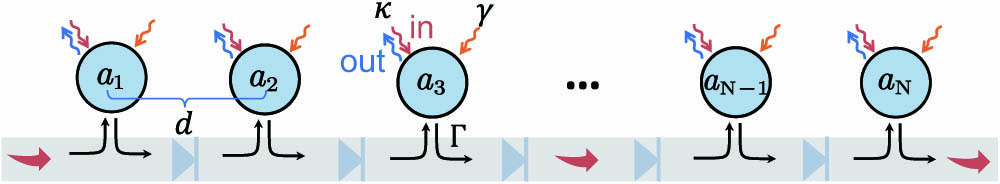
We considered a photonic network composed of an array of cavities and a nonreciprocal bus, as shown in Fig. 1. We focused on one photonic mode for each cavity, and the photonic modes of different cavities can be engineered to have an identical resonance frequency . The cavities were coupled to the nonreciprocal bus, which supports a continuum of right-propagating modes. The Hamiltonian of the photonic network reads , where corresponds to the cavities, and is the free Hamiltonian of the bus modes. The cavity-bus coupling can be modeled as , where , denotes the position of the th cavity, and is the coupling rate between the cavity mode and the bus modes . As the bus modes propagate unidirectionally from the left () to the right (), the wavevector satisfies , and can be expressed as , where is the group velocity of the bus mode and is determined by the loss rate.
Figure 1.Chain of photonic cavities with identical modes coupled to a nonreciprocal bus. The nonreciprocity of the bus can be enforced by inserting optical isolators between neighboring cavities. denotes the coupling between each cavity and the bus, is the input/output coupling rate of each cavity, is the net pumping rate (including internal damping), and is the spacing between neighboring cavities. Here, we take the natural unit of .
We used the input–output formalism to characterize the transport properties of the system. Under the Born–Markov approximation [57], the equations of motion for the amplitudes are given by where are input fields, , is the signal frequency, , and with is the attenuation length of the bus. for , for , and for . For simplicity, we assumed that the input/output coupling rates and pumping rates were identical for all cavities; i.e., and . As varies from to , the effective coupling between different cavities changed from short range to long range.
By Fourier transforming and considering the input–output boundary conditions [58], we obtained the input–output relation in the frequency domain where is the input/output amplitude vector. The nonreciprocal amplification can be captured by the scattering matrix . In particular, a large component in the bottom left corner of , as shown in Fig. 2(a), corresponds to a strong amplification of the input signal from the first cavity () to the last one ().
Figure 2.Scattering matrices for (a) and (b) with . (c) Gain for different system sizes as a function of the pumping rate . In all plots, , , , and .
From Eq. (2), we obtained an analytical solution for the scattering matrix,The coefficients are given by where is the frequency detuning. An amplification from the th cavity to the th cavity occurs when . When the separation is sufficiently large, we have for ; i.e., for zero detuning, while the attenuation occurs for .
Of particular interest was the long-range coupling case of . In this case, the condition of amplification becomes . This result suggests that any small cavity-bus coupling would suffice to sustain nonreciprocal amplification provided that the pumping overcomes the dissipation to the input–output ports. For , the amplitudes of all scattering matrix elements are less than unity, as shown in Fig. 2(b). When goes beyond the transition point [red dot in Fig. 2(c)], becomes larger than 1 and increases rapidly with , as depicted in Fig. 2(c). When is further increased beyond , the system enters an unstable regime denoted by the shaded area in Fig. 2(c). A stable system requires that the real parts of the eigenvalues of the non-Hermitian matrix should be negative; otherwise, any fluctuation would get exponentially amplified. In our case, the eigenvalues were degenerate and , and thus the system is stable only when .
3. RELATION BETWEEN AMPLIFICATION TRANSITION AND TOPOLOGICAL PHASE TRANSITION
The nonreciprocal amplification transition exhibited in the scattering matrix is rooted in the non-Hermitian dynamic matrix , which satisfies . If the system has only nearest-neighbor coupling between the cavities, a direct correspondence can be established between the nonreciprocal amplification and a nontrivial topological invariant defined with the spectrum of the dynamic matrix under a periodic boundary condition (PBC) [43]. However, as we will show later, this correspondence does not hold in our system for long-range coupling.
Under the PBC, the dynamic matrix is diagonal in the basis , where with , and represents the real-space wave function. The spectrum of reads where and . For more details, see Appendix A. Since is non-Hermitian, is in general complex with . Furthermore, since is periodic in with a period of , it describes a closed curve in the complex plane when varies from 0 to . Thus, we can define a winding number from the argument principle [48,59] The winding number is an integer and can be obtained by counting the number of times that wraps around the origin as varies from 0 to .
The topological phase transition occurs at the location where the real and the imaginary parts of are both zero for some . If the coupling range is much smaller than the system size () and the detuning is zero, the TPT condition is the same as the NAT condition in Eq. (5). However, in the case of long-range coupling with zero detuning, the TPT occurs at , which is different from the NAT condition. For more details, see Appendix A.
In Fig. 3, we present the gain as a function of the pumping rate and the attenuation length . Three regions can be clearly identified; i.e., the attenuation (left), the amplification (middle), and the unstable (right) regions. The topological phase transition of the dynamic matrix under the PBC (red dashed line) coincides with the amplification transition only for short-range coupling (), where the boundary effect is negligible. With increasing , the correspondence between the topological phase transition and the nonreciprocal amplification transition breaks down. As shown in Fig. 3, the TPT deviates drastically from the NAT when .
Figure 3.Gain as a function of the pumping rate and the attenuation length . The black dashed curve labeled by NAT corresponds to the nonreciprocal amplification transition, which agrees well with the topological phase transition (red dashed curve labeled by TPT) when . As increases, the NAT starts to deviate from the TPT. The white dashed curve indicates the critical pumping beyond which the system becomes unstable. For the simulation, we take , , and .
In Fig. 4, we show the gain for nonzero detuning to manifest the bandwidth of amplification as usually defined by the FWHM. We plot the gain as a function of frequency detuning and the pumping rate . The amplification bandwidth for various is indicated by the blue dash-dotted curve. We can see that the amplification bandwidth decreases with increasing , which is determined by Eq. (3).
Figure 4.Gain as a function of the pumping rate and the frequency detuning for long-range coupling (). The black dashed curve corresponds to unidirectional amplification transition. The blue dash-dotted curve corresponds to half maximum amplification for different , which indicates the amplification bandwidth. For the simulation, we take , , and .
Finally, we discuss other possible experimental realizations of the proposed model. Recently, nonreciprocal transport and amplification for short-range coupled models have been observed by optomechanical interactions [26,36,37], which can be adapted for the photonic network in this work. The whispering gallery modes in microresonators can be chirally coupled with a forward propagating wave in a tapered fiber, which can also be used to simulate the model here, and the attenuation length can be orders of magnitude longer than the length scale of the microresonator systems [60,61]. The photonic network also can be realized with photonic crystals [62,63] using time or spatial modulations [64–67], optical nonlinearities [68,69], or gyromagnetic and dielectric materials with artificial design [70,71]. Besides, the superconducting systems also provide a good platform to realize the nonreciprocal amplification [72,73]. Experimental parameters for specific platforms can be readily deduced from the theoretical framework in this work.
4. CONCLUSION
To conclude, we have studied the nonreciprocal amplification transition in a photonic network of cavities coupled to a nonreciprocal bus with unidirectional transmission. When the attenuation length of the bus is larger than the system size, an effective long-range coupling between the cavities can be established. We show that the correspondence between the nonreciprocal amplification transition and topological phase transition breaks down for long-range coupling, as the NAT deviates significantly from the TPT associated with the underlying dynamic matrix. We derived the exact analytical conditions for both the amplification transition and the topological phase transition for an arbitrary coupling range. We believe our work can be applied to signal transmission and amplification, and also paves the way to study the long-range coupling and nontrivial boundary effects in other topological and non-Hermitian systems.
APPENDIX A: DERIVATION OF DYNAMIC MATRIX UNDER PERIODIC BOUNDARY CONDITION
The dynamic matrix under PBC can be rewritten in the plane-wave basis as where . As and , we have which holds for any coupling range. We can define the winding number as the number of times that wraps around the origin when increases from 0 to , and a topological phase transition occurs when becomes zero; i.e.,
If the coupling range is much smaller than the system size and the detuning of the input signal is zero, the topological phase transition condition is simplified to By defining the parameter the topological phase transition condition can be rewritten as , provided that the system is in the stable regime with . This condition is consistent with the nonreciprocal amplification transition condition.
However, for long-range coupling (), the element of the dynamic matrix in Eq. (A2) becomes The topological phase transition condition in Eq. (A3) then becomes which is different from the amplification transition condition. Note that Eq. (A6) should not be derived from Eq. (A4). This observation suggests that one can no longer use the topological phase transition to predict the amplification transition in a system with long-range coupling.