
Wen-Long YAO, Xu-Guang GUO, Yi-Ming ZHU, Ping LI. Terahertz beam reconfigurable micro-strip Quasi-Yagi-Uda antenna based on monolayer graphene[J]. Journal of Infrared and Millimeter Waves, 2020, 39(1): 39
- Journal of Infrared and Millimeter Waves
- Vol. 39, Issue 1, 39 (2020)
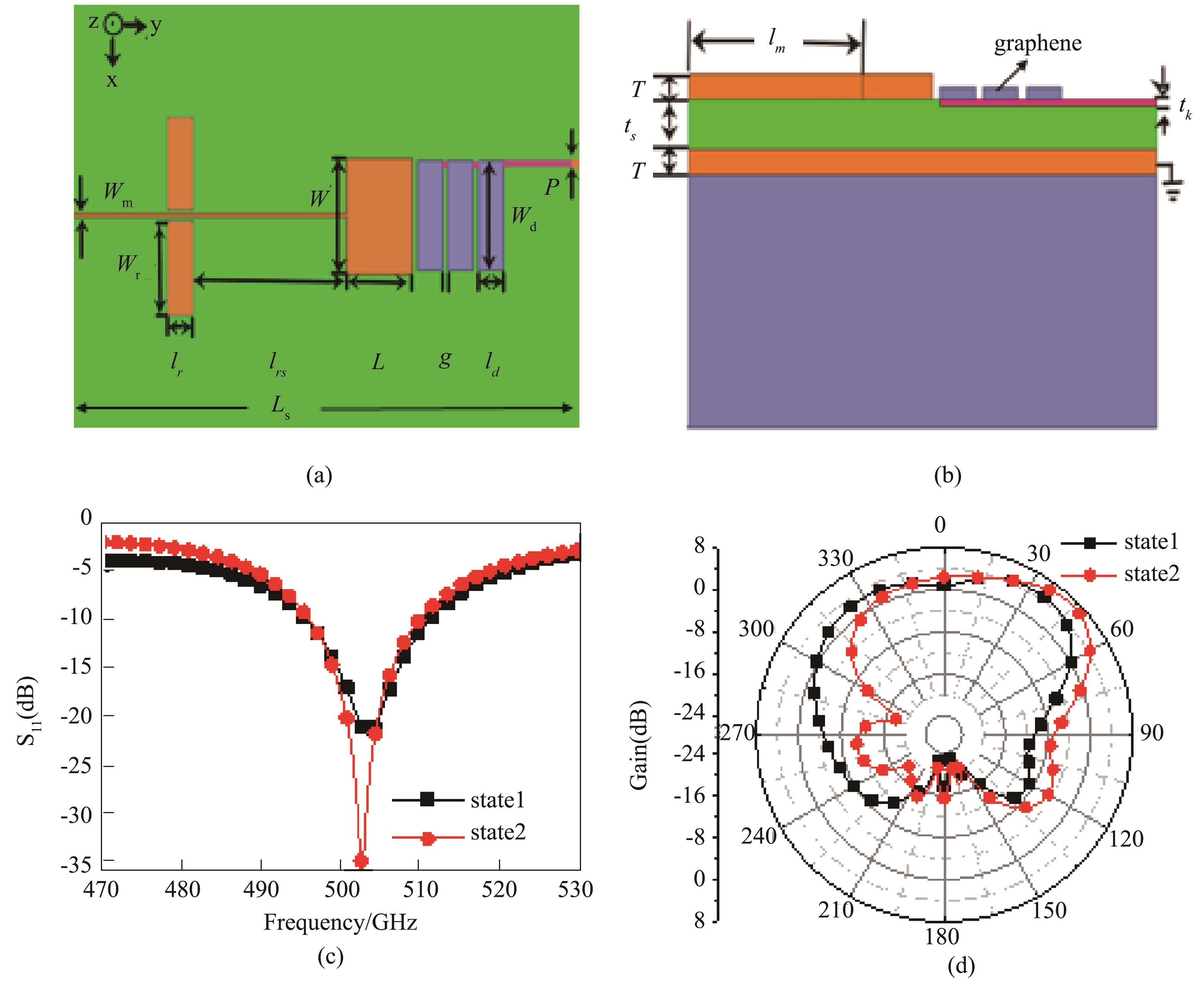
Fig. 1. Schematic of the proposed antenna and the basic performance parameters, (a) Top view, (b) Side view, (c) Reflection coefficient S11, and (d) Simulated radiation patterns in E-plane for the two working states of the antenna (states 1 and 2 for the cases of unbiased and biased)
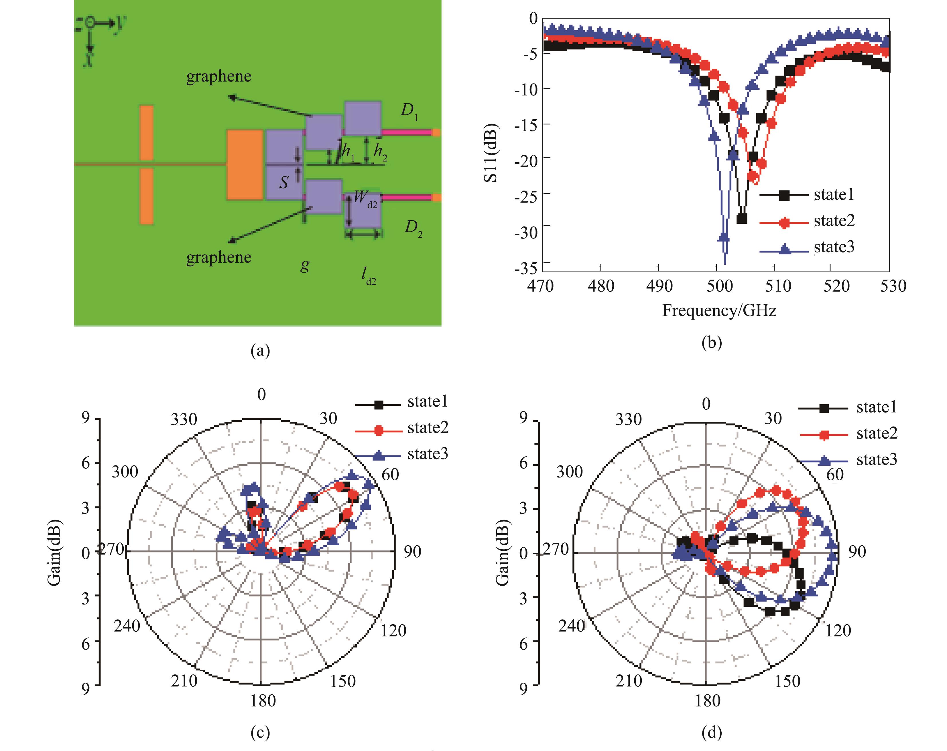
Fig. 2. (a) Schematic of the antenna with two groups of directors, (b)Reflection coefficient S 11, (c) E-plane radiation pattern and (d) θ =60° plane radiation pattern of the proposed antenna operating at different states.
Fig. 3. (a) Structure of the antenna with three groups of directors, (b) Reflection coefficient S11 of the proposed antenna operating at different states, (c) E-plane radiation pattern, and (d) Radiation pattern in θ =60° plane
Fig. 4. (a-1)~(a-4) and (b-1)~(b-4), 3D radiation patterns in different planes.(c-1)~(c-4) Surface current (Js) distributions for the proposed antenna in different working states. (a-1), (b-1), and (c-1) for state 1; (a-2), (b-2), and (c-2) for state 2; (a-3), (b-3), and (c-3) for state 3; (a-4), (b-4), and (c-4) for state 6.
Fig. 5. (a) and (b) Radiation patterns of antenna proposed in Section 2.2, (a) With different electron relaxation times in graphene, (b) With and without p-doped silicon strips,(c) and (d) Radiation patterns of antenna proposed in section 2.1, (c) With different bias voltages applied to the graphene-patch directors, and (d) With graphene-patch directors with µ c=0 eV and without graphene-patch directors.
|
Table 1. Antenna parameters (units: µm)
|
Table 2. Antenna performance

Set citation alerts for the article
Please enter your email address
© Copyright 2018-2021 | Chinese Laser Press. All Rights Reserved 沪ICP备15018463号-20