• Photonics Research
  • Vol. 10, Issue 4, 932 (2022)
Beichen Wang1、†, Zijiao Yang1、2、†, Shuman Sun1, and Xu Yi1、2、*
Author Affiliations
  • 1Department of Electrical and Computer Engineering, University of Virginia, Charlottesville, Virginia 22904, USA
  • 2Department of Physics, University of Virginia, Charlottesville, Virginia 22904, USA
  • show less
    DOI: 10.1364/PRJ.450103 Cite this Article Set citation alerts
    Beichen Wang, Zijiao Yang, Shuman Sun, Xu Yi. Radio-frequency line-by-line Fourier synthesis based on optical soliton microcombs[J]. Photonics Research, 2022, 10(4): 932 Copy Citation Text show less
    Concept of RF line-by-line Fourier synthesis with dual-microresonator solitons. A radio-frequency (RF) comb that is composed of a series of equidistant RF lines is created by photomixing two soliton microcombs with slightly different repetition frequencies on a photodiode (PD). The RF comb spacing is set by the repetition rate difference of the two soliton microcombs, and the RF comb offset frequency is nullified by using a common pump laser to drive both optical solitons. To implement line-by-line amplitude (An) and phase (φn) control of the RF comb lines, one of the optical microcombs (signal solitons) goes through optical line-by-line waveshaping, and optical amplitude modulations (AMs) and phase modulations (PMs) are down-converted to the RF frequency comb through dual-microcomb coherent sampling. As the RF frequency comb forms a complete Fourier series, arbitrary temporal waveforms can be synthesized.
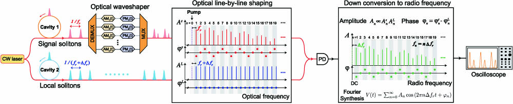
    Fig. 1. Concept of RF line-by-line Fourier synthesis with dual-microresonator solitons. A radio-frequency (RF) comb that is composed of a series of equidistant RF lines is created by photomixing two soliton microcombs with slightly different repetition frequencies on a photodiode (PD). The RF comb spacing is set by the repetition rate difference of the two soliton microcombs, and the RF comb offset frequency is nullified by using a common pump laser to drive both optical solitons. To implement line-by-line amplitude (An) and phase (φn) control of the RF comb lines, one of the optical microcombs (signal solitons) goes through optical line-by-line waveshaping, and optical amplitude modulations (AMs) and phase modulations (PMs) are down-converted to the RF frequency comb through dual-microcomb coherent sampling. As the RF frequency comb forms a complete Fourier series, arbitrary temporal waveforms can be synthesized.
    Line-by-line waveshaping of RF Gaussian waveforms. (a) Simplified experimental setup. The pump laser frequency is derived from the frequency of a continuous-wave (cw) laser, fL, and the voltage-controlled oscillator (VCO), fVCO. (b) Optical spectra of the signal (red) and local (blue) microresonator solitons. Sech2 envelope fittings are shown by dashed lines. The waveform synthesis is shown in (c)–(g) to illustrate the line-by-line control of the amplitude and phase of the RF comb. (c) Reference dual-microcomb waveforms with only dispersion compensation. (d) Amplitude control of the RF comb lines to shape temporal waveforms into Gaussian pulses with 235 ps pulse width. (e) Further amplitude control to add an equidistant Gaussian pulse and double the RF comb repetition frequency. (f) Adjust the relative Gaussian amplitudes through comb line amplitude control. (g) Combined amplitude and phase control of the RF comb to tune the relative position of the two Gaussian pulses. From top to bottom in each panel, we show (i) the optical spectra of soliton dual-microcomb after waveshaping, (ii) the down-converted RF spectra, (iii) the phase of RF comb lines, and (iv) the temporal waveforms. Designed comb line powers and phases are shown with red circles, and the designed temporal waveforms are shown with dashed blue lines.
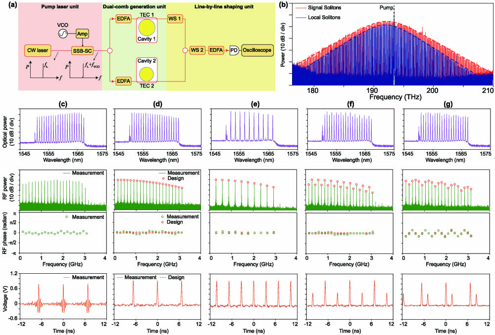
    Fig. 2. Line-by-line waveshaping of RF Gaussian waveforms. (a) Simplified experimental setup. The pump laser frequency is derived from the frequency of a continuous-wave (cw) laser, fL, and the voltage-controlled oscillator (VCO), fVCO. (b) Optical spectra of the signal (red) and local (blue) microresonator solitons. Sech2 envelope fittings are shown by dashed lines. The waveform synthesis is shown in (c)–(g) to illustrate the line-by-line control of the amplitude and phase of the RF comb. (c) Reference dual-microcomb waveforms with only dispersion compensation. (d) Amplitude control of the RF comb lines to shape temporal waveforms into Gaussian pulses with 235 ps pulse width. (e) Further amplitude control to add an equidistant Gaussian pulse and double the RF comb repetition frequency. (f) Adjust the relative Gaussian amplitudes through comb line amplitude control. (g) Combined amplitude and phase control of the RF comb to tune the relative position of the two Gaussian pulses. From top to bottom in each panel, we show (i) the optical spectra of soliton dual-microcomb after waveshaping, (ii) the down-converted RF spectra, (iii) the phase of RF comb lines, and (iv) the temporal waveforms. Designed comb line powers and phases are shown with red circles, and the designed temporal waveforms are shown with dashed blue lines.
    Arbitrary waveform generation by using dual-microcomb RF Fourier synthesis. (a) Triangle waveform. (b) Square waveform. (c) “UVA”-like waveform. The corresponding (i) optical spectra, (ii) RF spectra, (iii) comb line phases, and (iv) temporal waveforms are shown from top to bottom in each panel. Designed comb line powers and phases are shown with red circles, and the designed temporal waveforms are shown with dashed blue lines.
    Fig. 3. Arbitrary waveform generation by using dual-microcomb RF Fourier synthesis. (a) Triangle waveform. (b) Square waveform. (c) “UVA”-like waveform. The corresponding (i) optical spectra, (ii) RF spectra, (iii) comb line phases, and (iv) temporal waveforms are shown from top to bottom in each panel. Designed comb line powers and phases are shown with red circles, and the designed temporal waveforms are shown with dashed blue lines.
    Tuning the repetition frequency of the RF comb and temporal waveforms. (a) The RF comb repetition frequency is tuned by adjusting the repetition rate of local solitons. Small range tuning is realized by tuning the temperature of the local soliton microresonator with a thermoelectric cooler (TEC). Large range tuning is accomplished by generating local solitons in a microresonator with a slightly different radius. Soliton repetition rates are indicated in the figure legend. (b) and (c) show the electrical spectra and corresponding temporal waveforms at three different operating points indicated in (a). (d) Allan deviation of RF comb repetition rate at point I in (a).
    Fig. 4. Tuning the repetition frequency of the RF comb and temporal waveforms. (a) The RF comb repetition frequency is tuned by adjusting the repetition rate of local solitons. Small range tuning is realized by tuning the temperature of the local soliton microresonator with a thermoelectric cooler (TEC). Large range tuning is accomplished by generating local solitons in a microresonator with a slightly different radius. Soliton repetition rates are indicated in the figure legend. (b) and (c) show the electrical spectra and corresponding temporal waveforms at three different operating points indicated in (a). (d) Allan deviation of RF comb repetition rate at point I in (a).
    Theoretical analysis of effective number of bits (ENOB). (a) Theoretical limit of dual-comb AWG ENOB versus the comb line power for 50 GHz analog bandwidth. The minimum pump power required to achieve such comb line power in the single soliton microcomb state is also shown. In this calculation, we assume 3 dB loss between the microresonators and the photodiode, and a 4 dB noise figure for the optical post-amplifier. (b) ENOB comparison of dual-comb AWG and state-of-the-art commercial electronic AWG.
    Fig. 5. Theoretical analysis of effective number of bits (ENOB). (a) Theoretical limit of dual-comb AWG ENOB versus the comb line power for 50 GHz analog bandwidth. The minimum pump power required to achieve such comb line power in the single soliton microcomb state is also shown. In this calculation, we assume 3 dB loss between the microresonators and the photodiode, and a 4 dB noise figure for the optical post-amplifier. (b) ENOB comparison of dual-comb AWG and state-of-the-art commercial electronic AWG.
    Beichen Wang, Zijiao Yang, Shuman Sun, Xu Yi. Radio-frequency line-by-line Fourier synthesis based on optical soliton microcombs[J]. Photonics Research, 2022, 10(4): 932
    Download Citation