
Beichen Wang, Zijiao Yang, Shuman Sun, Xu Yi, "Radio-frequency line-by-line Fourier synthesis based on optical soliton microcombs," Photonics Res. 10, 932 (2022)
- Photonics Research
- Vol. 10, Issue 4, 932 (2022)
Abstract
1. INTRODUCTION
Fourier analysis creates one-to-one mapping between the temporal and frequency profiles of a waveform. Arbitrary temporal waveforms can be generated through Fourier synthesis by manipulating the spectral amplitude and phase in the frequency domain. Optical spectral waveshaping, or optical line-by-line waveshaping, has been widely applied to optical arbitrary waveform generation (AWG) [1,2], coherent control of quantum processes [3–5], and optical communications [6]. The broad optical bandwidth provides femtosecond temporal resolution in the Fourier synthesis [7] that is not attainable by conventional electronics.
Fourier synthesis in the optical domain can be down-converted to microwave and millimeter-wave frequencies [8–13] through the coherent dual-comb sampling method [14], and it could have wide applications in wireless communications, radar systems, and electronic testing [15–17]. When photomixing two optical frequency combs with different repetition rates on a photodiode, an RF frequency comb will be created, with its comb lines deriving their amplitudes and phases from the dual optical combs. Line-by-line amplitude and phase control on optical frequency combs [18] can then be coherently mapped to the RF frequency comb for waveform synthesis, which has been shown recently with electro-optic frequency combs [8–13]. Compared with other existing photonic methods for RF waveform generation [19–24], which rely on optical delay structures to either provide enough dispersion for far-field frequency-to-time mapping, or route different replicas of a low repetition rate optical pulse to different arrival times on a photodiode, the Fourier synthesis method eliminates the need for long tunable optical delay lines and low repetition rate mode-locked lasers, and thus creates the potential for mass-scale integration on a photonic chip.
In this work, we demonstrate RF spectral line-by-line waveshaping and Fourier synthesis of RF waveforms by using optical dual-microresonator solitons [25–28]. The high repetition rate of soliton microresonator-based frequency combs (microcombs) [28] enables line-by-line amplitude and phase control of individual optical comb lines [18]. Dual-comb coherent sampling is then used to coherently down-convert the waveshaped optical microcomb to RF frequencies by beating it with another soliton microcomb on a fast photodiode. A complete discrete Fourier series can be constructed for waveform synthesis by nullifying the carrier envelope offset frequency in the down-converted RF frequency comb. A series of temporal waveforms, including tunable Gaussian, triangle, square, and “UVA”-like logo, is demonstrated to illustrate arbitrary waveform synthesis. All critical components in the dual-microcomb method, including soliton microcombs [28], wavelength multiplexers/demultiplexers [29], intensity and phase modulators [30], optical amplifiers [31], and ultrafast photodiodes [32], are compatible with photonic integration. A discussion of waveform quality and a comparison of the effective number of bits (ENOB) with electronic AWG are presented at the end of the manuscript.
Sign up for Photonics Research TOC. Get the latest issue of Photonics Research delivered right to you!Sign up now
The concept of dual-microcomb RF line-by-line waveshaping is illustrated in Fig. 1. Signal solitons with repetition rate of
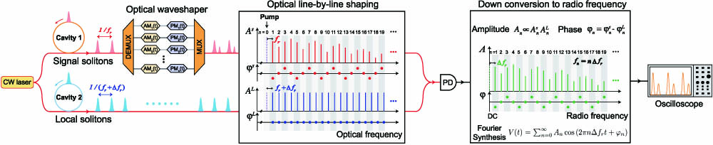
Figure 1.Concept of RF line-by-line Fourier synthesis with dual-microresonator solitons. A radio-frequency (RF) comb that is composed of a series of equidistant RF lines is created by photomixing two soliton microcombs with slightly different repetition frequencies on a photodiode (PD). The RF comb spacing is set by the repetition rate difference of the two soliton microcombs, and the RF comb offset frequency is nullified by using a common pump laser to drive both optical solitons. To implement line-by-line amplitude (
2. EXPERIMENTAL METHODS
In our experiment, the signal and local solitons are generated in SiN micro-ring resonators [35] with intrinsic quality factors of
![]()
Figure 2.Line-by-line waveshaping of RF Gaussian waveforms. (a) Simplified experimental setup. The pump laser frequency is derived from the frequency of a continuous-wave (cw) laser,
An optical line-by-line waveshaper [18] is used to control the phase of each comb line in the signal solitons (
3. RESULTS
To illustrate line-by-line waveshaping in the RF domain, four types of Gaussian based temporal waveforms are demonstrated in Figs. 2(d)–2(g). The fundamental Gaussian waveform is shown in Fig. 2(d), which has a Gaussian envelope with flat phase in both the frequency and temporal domains. The power and phase of the generated RF comb match the designed ones very well, which are shown in red circles. The corresponding temporal waveform is a Gaussian pulse train with a time period of 6.71 ns, peak voltage of 0.94 V, and pulse width of 235 ps. No electrical amplifier after the photodiode is used in this work. The number of pulses in one period can be doubled by knocking out half of the RF comb lines [Fig. 2(e)]. This is equivalent to adding an equidistant Gaussian pulse with the same amplitude in one temporal period. The amplitude of the added Gaussian pulse can be adjusted by changing the amplitude of the RF comb [Fig. 2(f)]. Finally, the temporal position of the added Gaussian pulse can be shifted by modifying both the amplitude and the phase of the RF comb lines [Fig. 2(g)]. The demonstration of these four Gaussian waveforms illustrates the full control of amplitude and phase in our RF line-by-line shaping method.
One direct application of line-by-line waveshaping is AWG. Three representative waveforms, including triangle, square, and “UVA”-like waveforms, are demonstrated here. For each temporal waveform, the corresponding amplitude and phase of each comb line can be derived by discrete Fourier transform of the temporal waveform. The Fourier transform of the triangle waveform is
![]()
Figure 3.Arbitrary waveform generation by using dual-microcomb RF Fourier synthesis. (a) Triangle waveform. (b) Square waveform. (c) “UVA”-like waveform. The corresponding (i) optical spectra, (ii) RF spectra, (iii) comb line phases, and (iv) temporal waveforms are shown from top to bottom in each panel. Designed comb line powers and phases are shown with red circles, and the designed temporal waveforms are shown with dashed blue lines.
As the RF waveform repetition period is set by the repetition rate difference between the signal and local solitons, it can be tuned directly by adjusting the repetition rate of one of the solitons. Small range tuning of repetition period can be achieved by adjusting the temperature of the local soliton microresonator. Figure 4(a) presents the RF comb repetition rate versus the temperature of the local soliton microresonator, and a tuning rate of
![]()
Figure 4.Tuning the repetition frequency of the RF comb and temporal waveforms. (a) The RF comb repetition frequency is tuned by adjusting the repetition rate of local solitons. Small range tuning is realized by tuning the temperature of the local soliton microresonator with a thermoelectric cooler (TEC). Large range tuning is accomplished by generating local solitons in a microresonator with a slightly different radius. Soliton repetition rates are indicated in the figure legend. (b) and (c) show the electrical spectra and corresponding temporal waveforms at three different operating points indicated in (a). (d) Allan deviation of RF comb repetition rate at point I in (a).
4. DISCUSSION
An important figure of merit for RF AWG is the effective number of bits (ENOB) [37], which can be used to evaluate the waveform quality or the effective resolution of the waveforms. For our dual-comb AWG method, the fundamental limit of its ENOB is set by the optical power of the frequency combs. The fundamental limit of the ENOB in the dual-comb AWG method can be calculated using the ratio of signal voltage to the root-mean-square noise voltage fluctuations, and it is defined as
For Kerr soliton microcombs, the comb line power at the envelope center (
![]()
Figure 5.Theoretical analysis of effective number of bits (ENOB). (a) Theoretical limit of dual-comb AWG ENOB versus the comb line power for 50 GHz analog bandwidth. The minimum pump power required to achieve such comb line power in the single soliton microcomb state is also shown. In this calculation, we assume 3 dB loss between the microresonators and the photodiode, and a 4 dB noise figure for the optical post-amplifier. (b) ENOB comparison of dual-comb AWG and state-of-the-art commercial electronic AWG.
The ultrahigh analog bandwidth has been the key advantage of photonic AWG systems. A 60 GHz analog bandwidth has been achieved previously using frequency-to-time mapping [19] and direct time-domain synthesis [23]. The analog bandwidth of the dual-comb Fourier synthesis method is ultimately limited by the Nyquist frequency of optical coherent sampling [14], i.e., half of the optical frequency comb repetition rate, and the bandwidth of the photodiode. The Nyquist frequency of dual-microcomb can range from a few gigahertz to a few hundred gigahertz [40,41]. The high Nyquist frequency has been applied to increase the bandwidth or sampling rate in dual-microcomb spectroscopy [27,33], Lidar [42,43], and imaging [44,45]. In terms of photodiodes, bandwidth exceeding hundreds of GHz has been demonstrated, and has been combined with soliton microcombs to generate RF signals with exceptional performance in power [46], phase noise [47,48], and time jitter [49]. It is thus possible to extend the analog bandwidth of dual-microcomb AWG beyond 100 GHz. In addition, all the critical components in dual-microcomb Fourier synthesis, including lasers, Kerr microresonators, multiplexers/demultiplexers, modulators, amplifiers, and ultrafast photodiodes, have been shown to be compatible with silicon photonics integration. Also, it eliminates the need for low-rate mode-locked lasers and long tunable delay lines required by the previous proposed on-chip solutions [19,23,24], and has the potential for mass production on a photonic chip. Finally, the time-bandwidth product (TBWP) of our current static arbitrary waveform demonstration is limited by the number of comb lines, which gives a maximum TBWP of 20. In contrast, a TBWP of 600 has been demonstrated by combining frequency-to-time mapping and optical interferometry [20]. In the future, the TBWP of our method can be increased dramatically by replacing the static waveshaper with phase and amplitude modulators for dynamic line-by-line phase and amplitude control [6,12,30], and the time aperture of the waveforms will be directly set by the time aperture of the modulation signals.
In summary, we have demonstrated arbitrary RF waveform generation through spectral line-by-line shaping with optical dual-microresonator solitons. In our experiment, the analog bandwidth of the waveform is 3 GHz, which is set purposely such that the waveform bandwidth will not exceed our oscilloscope bandwidth. The waveform analog bandwidth in our dual-microcomb method can be conveniently increased by adjusting the free spectral range (FSR) difference between the two soliton microresonators, which can be precisely controlled in microfabrication. In addition, although the demonstrated waveform generation is periodic and static, dynamic waveform generation can be implemented by using time varying amplitude and phase modulation of the optical comb lines through integrated photonic modulators [6,12,30].
Acknowledgment
Acknowledgment. The authors thank Ligentec for resonator fabrication.
References
[1] Z. Jiang, C.-B. Huang, D. E. Leaird, A. M. Weiner. Optical arbitrary waveform processing of more than 100 spectral comb lines. Nat. Photonics, 1, 463-467(2007).
[2] S. T. Cundiff, A. M. Weiner. Optical arbitrary waveform generation. Nat. Photonics, 4, 760-766(2010).
[3] D. Goswami. Optical pulse shaping approaches to coherent control. Phys. Rep., 374, 385-481(2003).
[4] M. C. Stowe, F. C. Cruz, A. Marian, J. Ye. High resolution atomic coherent control via spectral phase manipulation of an optical frequency comb. Phys. Rev. Lett., 96, 153001(2006).
[5] I. Barmes, S. Witte, K. S. Eikema. Spatial and spectral coherent control with frequency combs. Nat. Photonics, 7, 38-42(2013).
[6] D. J. Geisler, N. K. Fontaine, T. He, R. P. Scott, L. Paraschis, J. P. Heritage, S. Yoo. Modulation-format agile, reconfigurable Tb/s transmitter based on optical arbitrary waveform generation. Opt. Express, 17, 15911-15925(2009).
[7] H.-S. Chan, Z.-M. Hsieh, W.-H. Liang, A. Kung, C.-K. Lee, C.-J. Lai, R.-P. Pan, L.-H. Peng. Synthesis and measurement of ultrafast waveforms from five discrete optical harmonics. Science, 331, 1165-1168(2011).
[8] V. Durán, S. Tainta, V. Torres-Company. Ultrafast electrooptic dual-comb interferometry. Opt. Express, 23, 30557-30569(2015).
[9] V. Durán, P. A. Andrekson, V. Torres-Company. Electro-optic dual-comb interferometry over 40 nm bandwidth. Opt. Lett., 41, 4190-4193(2016).
[10] F. Ferdous, D. E. Leaird, C.-B. Huang, A. Weiner. Dual-comb electric-field cross-correlation technique for optical arbitrary waveform characterization. Opt. Lett., 34, 3875-3877(2009).
[11] X. Zhou, X. Zheng, H. Wen, H. Zhang, B. Zhou. Pair-by-pair pulse shaping for optical arbitrary waveform generation by dual-comb heterodyne. Opt. Lett., 38, 5331-5333(2013).
[12] F. Yin, Z. Yin, X. Xie, Y. Dai, K. Xu. Broadband radio-frequency signal synthesis by photonic-assisted channelization. Opt. Express, 29, 17839-17848(2021).
[13] V. Ataie, D. Esman, B.-P. Kuo, N. Alic, S. Radic. Subnoise detection of a fast random event. Science, 350, 1343-1346(2015).
[14] I. Coddington, W. Swann, N. Newbury. Coherent linear optical sampling at 15 bits of resolution. Opt. Lett., 34, 2153-2155(2009).
[15] J.-W. Lin, C.-L. Lu, H.-P. Chuang, F.-M. Kuo, J.-W. Shi, C.-B. Huang, C.-L. Pan. Photonic generation and detection of W-band chirped millimeter-wave pulses for radar. IEEE Photon. Technol. Lett., 24, 1437-1439(2012).
[16] P. Ghelfi, F. Laghezza, F. Scotti, G. Serafino, A. Capria, S. Pinna, D. Onori, C. Porzi, M. Scaffardi, A. Malacarne, V. Vercesi, E. Lazzeri, F. Berizzi, A. Bogoni. A fully photonics-based coherent radar system. Nature, 507, 341-345(2014).
[17] I. S. Lin, J. D. McKinney, A. M. Weiner. Photonic synthesis of broadband microwave arbitrary waveforms applicable to ultra-wideband communication. IEEE Microw. Wireless Compon. Lett., 15, 226-228(2005).
[18] F. Ferdous, H. Miao, D. E. Leaird, K. Srinivasan, J. Wang, L. Chen, L. T. Varghese, A. M. Weiner. Spectral line-by-line pulse shaping of on-chip microresonator frequency combs. Nat. Photonics, 5, 770-776(2011).
[19] M. H. Khan, H. Shen, Y. Xuan, L. Zhao, S. Xiao, D. E. Leaird, A. M. Weiner, M. Qi. Ultrabroad-bandwidth arbitrary radiofrequency waveform generation with a silicon photonic chip-based spectral shaper. Nat. Photonics, 4, 117-122(2010).
[20] A. Rashidinejad, A. M. Weiner. Photonic radio-frequency arbitrary waveform generation with maximal time-bandwidth product capability. J. Lightwave Technol., 32, 3383-3393(2014).
[21] A. Rashidinejad, D. E. Leaird, A. M. Weiner. Ultrabroadband radio-frequency arbitrary waveform generation with high-speed phase and amplitude modulation capability. Opt. Express, 23, 12265-12273(2015).
[22] A. Rashidinejad, Y. Li, A. M. Weiner. Recent advances in programmable photonic-assisted ultrabroadband radio-frequency arbitrary waveform generation. IEEE J. Quantum Electron., 52, 0600117(2015).
[23] J. Wang, H. Shen, L. Fan, R. Wu, B. Niu, L. T. Varghese, Y. Xuan, D. E. Leaird, X. Wang, F. Gan, A. M. Weiner, M. Qi. Reconfigurable radio-frequency arbitrary waveforms synthesized in a silicon photonic chip. Nat. Commun., 6, 5957(2015).
[24] M. Tan, X. Xu, A. Boes, B. Corcoran, J. Wu, T. G. Nguyen, S. T. Chu, B. E. Little, R. Morandotti, A. Mitchell, D. J. Moss. Photonic rf arbitrary waveform generator based on a soliton crystal micro-comb source. J. Lightwave Technol., 38, 6221-6226(2020).
[25] T. Herr, V. Brasch, J. Jost, C. Wang, N. Kondratiev, M. Gorodetsky, T. Kippenberg. Temporal solitons in optical microresonators. Nat. Photonics, 8, 145-152(2014).
[26] V. Brasch, M. Geiselmann, T. Herr, G. Lihachev, M. Pfeiffer, M. Gorodetsky, T. Kippenberg. Photonic chip–based optical frequency comb using soliton Cherenkov radiation. Science, 351, 357-360(2016).
[27] M.-G. Suh, Q.-F. Yang, K. Y. Yang, X. Yi, K. J. Vahala. Microresonator soliton dual-comb spectroscopy. Science, 354, 600-603(2016).
[28] T. J. Kippenberg, A. L. Gaeta, M. Lipson, M. L. Gorodetsky. Dissipative Kerr solitons in optical microresonators. Science, 361, eaan8083(2018).
[29] A. Rahim, J. Goyvaerts, B. Szelag, J.-M. Fedeli, P. Absil, T. Aalto, M. Harjanne, C. Littlejohns, G. Reed, G. Winzer, S. Lischke, L. Zimmermann, D. Knoll, D. Geuzebroek, A. Leinse, M. Geiselmann, M. Zervas, H. Jans, A. Stassen, C. Domínguez, P. Muñoz, D. Domenech, A. L. Giesecke, M. C. Lemme, R. Baets. Open-access silicon photonics platforms in Europe. IEEE J. Sel. Top. Quantum Electron., 25, 8200818(2019).
[30] C. Wang, M. Zhang, X. Chen, M. Bertrand, A. Shams-Ansari, S. Chandrasekhar, P. Winzer, M. Lončar. Integrated lithium niobate electro-optic modulators operating at cmos-compatible voltages. Nature, 562, 101-104(2018).
[31] C. O. de Beeck, B. Haq, L. Elsinger, A. Gocalinska, E. Pelucchi, B. Corbett, G. Roelkens, B. Kuyken. Heterogeneous III-V on silicon nitride amplifiers and lasers via microtransfer printing. Optica, 7, 386-393(2020).
[32] Q. Yu, J. Gao, N. Ye, B. Chen, K. Sun, L. Xie, K. Srinivasan, M. Zervas, G. Navickaite, M. Geiselmann, A. Beling. Heterogeneous photodiodes on silicon nitride waveguides. Opt. Express, 28, 14824-14830(2020).
[33] A. Dutt, C. Joshi, X. Ji, J. Cardenas, Y. Okawachi, K. Luke, A. L. Gaeta, M. Lipson. On-chip dual-comb source for spectroscopy. Sci. Adv., 4, e1701858(2018).
[34] B. Wang, Z. Yang, X. Zhang, X. Yi. Vernier frequency division with dual-microresonator solitons. Nat. Commun., 11, 3975(2020).
[35] M. H. Pfeiffer, A. Kordts, V. Brasch, M. Zervas, M. Geiselmann, J. D. Jost, T. J. Kippenberg. Photonic damascene process for integrated high-
[36] J. R. Stone, T. C. Briles, T. E. Drake, D. T. Spencer, D. R. Carlson, S. A. Diddams, S. B. Papp. Thermal and nonlinear dissipative-soliton dynamics in Kerr-microresonator frequency combs. Phys. Rev. Lett., 121, 063902(2018).
[38] X. Yi, Q.-F. Yang, K. Y. Yang, M.-G. Suh, K. Vahala. Soliton frequency comb at microwave rates in a high-
[39] J. F. Bauters, J. R. Adleman, M. J. Heck, J. E. Bowers. Design and characterization of arrayed waveguide gratings using ultra-low loss Si3N4 waveguides. Appl. Phys. A, 116, 427-432(2014).
[40] M.-G. Suh, K. Vahala. Gigahertz-repetition-rate soliton microcombs. Optica, 5, 65-66(2018).
[41] Q. Li, T. C. Briles, D. A. Westly, T. E. Drake, J. R. Stone, B. R. Ilic, S. A. Diddams, S. B. Papp, K. Srinivasan. Stably accessing octave-spanning microresonator frequency combs in the soliton regime. Optica, 4, 193-203(2017).
[42] M.-G. Suh, K. J. Vahala. Soliton microcomb range measurement. Science, 359, 884-887(2018).
[43] P. Trocha, M. Karpov, D. Ganin, M. H. Pfeiffer, A. Kordts, S. Wolf, J. Krockenberger, P. Marin-Palomo, C. Weimann, S. Randel, W. Freude, T. J. Kippenberg, C. Koos. Ultrafast optical ranging using microresonator soliton frequency combs. Science, 359, 887-891(2018).
[44] X. Yi, Q.-F. Yang, K. Y. Yang, K. Vahala. Imaging soliton dynamics in optical microcavities. Nat. Commun., 9, 1(2018).
[45] C. Bao, M.-G. Suh, K. Vahala. Microresonator soliton dual-comb imaging. Optica, 6, 1110-1116(2019).
[46] B. Wang, J. S. Morgan, K. Sun, M. Jahanbozorgi, Z. Yang, M. Woodson, S. Estrella, A. Beling, X. Yi. Towards high-power, high-coherence, integrated photonic mmwave platform with microcavity solitons. Light Sci. Appl., 10, 1(2021).
[47] S. Zhang, J. M. Silver, X. Shang, L. Del Bino, N. M. Ridler, P. Del’Haye. Terahertz wave generation using a soliton microcomb. Opt. Express, 27, 35257-35266(2019).
[48] T. Tetsumoto, F. Ayano, M. Yeo, J. Webber, T. Nagatsuma, A. Rolland. 300 GHz wave generation based on a Kerr microresonator frequency comb stabilized to a low noise microwave reference. Opt. Lett., 45, 4377-4380(2020).
[49] D. Jeong, D. Kwon, I. Jeon, I. H. Do, J. Kim, H. Lee. Ultralow jitter silica microcomb. Optica, 7, 1108-1111(2020).


Set citation alerts for the article
Please enter your email address

© Copyright 2018-2021 | Chinese Laser Press. All Rights Reserved 沪ICP备15018463号-20