• Opto-Electronic Advances
  • Vol. 6, Issue 2, 220012 (2023)
Huan Zhao1、2, Xinke Wang2, Shutian Liu1、*, and Yan Zhang2、**
Author Affiliations
  • 1Department of Physics, Harbin Institute of Technology, Harbin 150001, China
  • 2Beijing Key Laboratory of Metamaterials and Devices, Key Laboratory of Terahertz Optoelectronics, Ministry of Education, Beijing Advanced Innovation Center for Imaging Theory and Technology, Department of Physics, Capital Normal University, Beijing 100048, China
  • show less
    DOI: 10.29026/oea.2023.220012 Cite this Article
    Huan Zhao, Xinke Wang, Shutian Liu, Yan Zhang. Highly efficient vectorial field manipulation using a transmitted tri-layer metasurface in the terahertz band[J]. Opto-Electronic Advances, 2023, 6(2): 220012 Copy Citation Text show less
    Schematic of the designed vectorial hologram metasurface device. Different holograms in eight polarization channels can be generated when the circularly polarized THz wave impinges on the metasurface, because the phase and polarization of the transmitted THz wave can be individually modulated. The hologram in a channel can be hidden by choosing the corresponding detected polarization state.
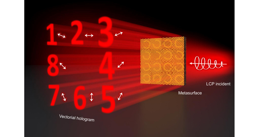
    Fig. 1. Schematic of the designed vectorial hologram metasurface device. Different holograms in eight polarization channels can be generated when the circularly polarized THz wave impinges on the metasurface, because the phase and polarization of the transmitted THz wave can be individually modulated. The hologram in a channel can be hidden by choosing the corresponding detected polarization state.
    Schematic and characteristics of the designed unit cell. (a) Concept of the designed tri-layer metasurface. The unit cell consists of three metal structure layers and two polyimide (PI) space layers. The top and bottom metallic layers are metagratings, and the middle metallic layer is a C-shaped split-ring antenna array. The thickness of the PI layers is 40 μm, and the thickness of the metal structure layers is 150 nm. (b–d) Top views of the top, middle, and bottom metal layers of the unit. The period of the structure P is 100 μm; θ andθ–90° are the angles between the metagrating direction and x-axis for the top and bottom layers, respectively; θ+45° is the angle between the symmetric axis of the C-shaped antenna and x-axis; 2α is the opening angle of the antenna; w and d are the width and period of the metagrating, which are 10 μm and 20 μm, respectively; r and R are the inner and outer radii of the antenna, which are 35 μm and 45 μm, respectively. (e) Transmitted spectrum of the metasurface with θ = 90°. The incident wave is x-polarized, and the transmitted light is y-polarized. (f) Amplitude and phase modulation of the eight selected antennas at 0.75 THz. Antennas 1 to 4 have opening angles 2α = 130, 96, 50, and 14°, and the angle between the symmetric axis and x-axis is –45°. Antennas 5 to 8 have the same opening angle as the first four antennas with a symmetric axis at 45°.
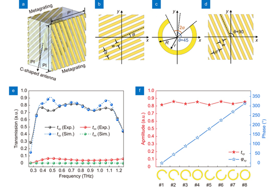
    Fig. 2. Schematic and characteristics of the designed unit cell. (a) Concept of the designed tri-layer metasurface. The unit cell consists of three metal structure layers and two polyimide (PI) space layers. The top and bottom metallic layers are metagratings, and the middle metallic layer is a C-shaped split-ring antenna array. The thickness of the PI layers is 40 μm, and the thickness of the metal structure layers is 150 nm. (bd) Top views of the top, middle, and bottom metal layers of the unit. The period of the structure P is 100 μm; θ andθ–90° are the angles between the metagrating direction and x-axis for the top and bottom layers, respectively; θ+45° is the angle between the symmetric axis of the C-shaped antenna and x-axis; 2α is the opening angle of the antenna; w and d are the width and period of the metagrating, which are 10 μm and 20 μm, respectively; r and R are the inner and outer radii of the antenna, which are 35 μm and 45 μm, respectively. (e) Transmitted spectrum of the metasurface with θ = 90°. The incident wave is x-polarized, and the transmitted light is y-polarized. (f) Amplitude and phase modulation of the eight selected antennas at 0.75 THz. Antennas 1 to 4 have opening angles 2α = 130, 96, 50, and 14°, and the angle between the symmetric axis and x-axis is 45°. Antennas 5 to 8 have the same opening angle as the first four antennas with a symmetric axis at 45°.
    Schematic and characteristics of the designed THz metasurface polarization analyzer. (a) Schematic of the working process of the THz metasurface polarization analyzer. An x-polarized THz wave is incident onto a THz half-wave plate (THWP), and the fast axis of the THWP is along the β/2 direction. The output THz wave is β-polarized and then incident on the metasurface device. The transmitted wave is transferred to the cross-polarization state, which is along the β–90° direction and focused on the focal plane. The amplitude distribution of the focal spot is along the θ direction. (b1–b4) Simulated amplitude distributions on the focal plane for β = 0, 45°, 90°, and 135°, respectively. Each white arrow represents the incident polarization state. (c1–c4) Experimental amplitude distributions on the focal plane for β = 0, 45°, 90°, and 135°, respectively. (d1)–(d4) Amplitude distribution curves extracted from the amplitude distributions along the black dashed circle in Fig. 3(b) for β = 0, 45°, 90°, and 135°, where the gray and red curves represent the simulated and experimental results, respectively.
    Fig. 3. Schematic and characteristics of the designed THz metasurface polarization analyzer. (a) Schematic of the working process of the THz metasurface polarization analyzer. An x-polarized THz wave is incident onto a THz half-wave plate (THWP), and the fast axis of the THWP is along the β/2 direction. The output THz wave is β-polarized and then incident on the metasurface device. The transmitted wave is transferred to the cross-polarization state, which is along the β–90° direction and focused on the focal plane. The amplitude distribution of the focal spot is along the θ direction. (b1b4) Simulated amplitude distributions on the focal plane for β = 0, 45°, 90°, and 135°, respectively. Each white arrow represents the incident polarization state. (c1c4) Experimental amplitude distributions on the focal plane for β = 0, 45°, 90°, and 135°, respectively. (d1)–(d4) Amplitude distribution curves extracted from the amplitude distributions along the black dashed circle in Fig. 3(b) for β = 0, 45°, 90°, and 135°, where the gray and red curves represent the simulated and experimental results, respectively.
    Schematic of a vectorial hologram device. (a) Arrangement of the vectorial hologram device. The white arrow represents the polarization of the output wave through each big cell. (b) Schematic of the selected 64 C-shaped antennas, where 2α is the opening angle of the antennas, and θ represents the polarization angle of the output wave. (c) Amplitude and phase modulation of the transmitted cross-polarized wave for the 64 selected cells. The bars represent the phase modulation, and the blue dashed curves through the red stars represent the amplitude modulation. (d) Top-view microscope image of part of the fabricated device, where the white bar represents 500 μm. (e–g) Top-view microscope images of the top, middle, and bottom device layers, respectively. The white bar represents 50 μm.
    Fig. 4. Schematic of a vectorial hologram device. (a) Arrangement of the vectorial hologram device. The white arrow represents the polarization of the output wave through each big cell. (b) Schematic of the selected 64 C-shaped antennas, where 2α is the opening angle of the antennas, and θ represents the polarization angle of the output wave. (c) Amplitude and phase modulation of the transmitted cross-polarized wave for the 64 selected cells. The bars represent the phase modulation, and the blue dashed curves through the red stars represent the amplitude modulation. (d) Top-view microscope image of part of the fabricated device, where the white bar represents 500 μm. (eg) Top-view microscope images of the top, middle, and bottom device layers, respectively. The white bar represents 50 μm.
    Experimental results for the image-hiding device. (a) Amplitude distribution of a hologram with no polarization state selected for detection. (b–i) Amplitude distributions when an image is hidden in channels C1 to C8, respectively, with the detected polarizations chosen as 67.5°, 90°, 112.5°, 135°, 157.5°, 0°, 22.5°, and 45°, respectively. Each white arrow represents the designed polarization state of the corresponding channel.
    Fig. 5. Experimental results for the image-hiding device. (a) Amplitude distribution of a hologram with no polarization state selected for detection. (bi) Amplitude distributions when an image is hidden in channels C1 to C8, respectively, with the detected polarizations chosen as 67.5°, 90°, 112.5°, 135°, 157.5°, 0°, 22.5°, and 45°, respectively. Each white arrow represents the designed polarization state of the corresponding channel.
    Experimental amplitudes for the image-hiding device. The colored curves are extracted from Fig. 5(b–i) with the detected polarization states being 67.5°, 90°, 112.5°, 135°, 157.5°, 0°, 22.5°, and 45°, respectively. Each red arrow represents the designed polarization state of the hidden channel.
    Fig. 6. Experimental amplitudes for the image-hiding device. The colored curves are extracted from Fig. 5(b–i) with the detected polarization states being 67.5°, 90°, 112.5°, 135°, 157.5°, 0°, 22.5°, and 45°, respectively. Each red arrow represents the designed polarization state of the hidden channel.
    Huan Zhao, Xinke Wang, Shutian Liu, Yan Zhang. Highly efficient vectorial field manipulation using a transmitted tri-layer metasurface in the terahertz band[J]. Opto-Electronic Advances, 2023, 6(2): 220012
    Download Citation