1Department of Physics, Harbin Institute of Technology, Harbin 150001, China
2Beijing Key Laboratory of Metamaterials and Devices, Key Laboratory of Terahertz Optoelectronics, Ministry of Education, Beijing Advanced Innovation Center for Imaging Theory and Technology, Department of Physics, Capital Normal University, Beijing 100048, China
Huan Zhao, Xinke Wang, Shutian Liu, Yan Zhang. Highly efficient vectorial field manipulation using a transmitted tri-layer metasurface in the terahertz band[J]. Opto-Electronic Advances, 2023, 6(2): 220012
Copy Citation Text
Polarization is a basic characteristic of electromagnetic waves that conveys much optical information owing to its many states. The polarization state is manipulated and controlled for optical information security, optical encryption, and optical communication. Metasurface devices provide a new way to manipulate wave-fronts of light. A single ultrathin metasurface device can generate and modulate several differently polarized light fields, and thus carries optical information in several different channels. Terahertz (THz) waves have become widely used as carrier waves for wireless communication. Compact and functional metasurface devices are in high demand for THz elements and systems. This paper proposes a tri-layer metallic THz metasurface for multi-channel polarization generation and phase modulation with a high efficiency of approximately 80%. An azimuthally polarized THz vectorial beam generator is realized and characterized for use as a THz polarization analyzer. The incident polarization angle can be observed graphically with high accuracy. Moreover, a vectorial hologram with eight channels for different linear polarization states is demonstrated experimentally. The information in different holograms can be hidden by choosing the polarization channel for detection. This work contributes to achieving multi-functional metasurface in the THz band and can benefit THz communication and optical information security.
Introduction
Terahertz (THz) waves have attracted increasing attention for decades because of their distinctive properties such as low photon energy and fingerprint spectra for materials. They have been widely applied for non-destructive detection1-3, security checking4,5, and biomedical science6,7. The high carrier frequencies of THz waves promise unprecedented channel capacity, which makes them candidates for carrier waves in wireless communication8,9. However, traditional THz elements are bulky owing to the longer wavelengths of THz waves. Moreover, THz devices have low efficiency because of the lack of THz-transparent materials. The emergence of metasurfaces provides new possibilities for THz elements and devices. THz metasurface devices such as absorbers10,11, metalenses12-14, and wave-plates15-17 have been demonstrated. These provide a new approach for constructing THz systems.
Metasurfaces are widely used to manipulate electromagnetic wave-fronts owing to their multiple geometric parameters18-21. When metasurfaces were first used, only the phase for the specified polarized state could be modulated. Many functional metasurface devices were achieved such as abnormal refractors22-24, polarization elements25,26, special beam generators27-29, and meta-hologram devices30-33. Along with the rapid development of material science and fabrication technology, the properties of electromagnetic waves can be modulated more freely and their functions became more varied. Metasurface devices are becoming increasingly practical and multi-functional34-37. Moreover, the amplitude, phase, and polarization of electromagnetic waves can be individually modulated simultaneously38, which provides an opportunity to generate and modulate vectorial optical fields. Versatile polarization control plays a key role for a functional metasurface. Anisotropic dielectric metasurfaces have different effective refractive indexes along two birefringent principal axes and allow increased control of polarization states39. The phase of the transmitted wave can be modulated by adjusting the geometric parameters along the two principal axes, and rotating the whole structure by an angle can modify the polarization of the transmitted wave. Such a metasurface is highly efficient because using dielectric materials avoids metallic ohmic loss. Special vectorial beams40,41, polarization-sensitive metalenses42-44, and holograms45-50 have been demonstrated using this kind of metasurface, thus giving rise to multi-channel functional devices. On one hand, it is difficult to fabricate dielectric metasurfaces in the THz band owing to the large wavelength of THz waves (several hundred micrometers). On the other hand, a bilayer diatomic metasurface has been designed for vectorial field control in the visible band based on the detour phase method51,52. The device includes a layer with a periodic metallic antenna array and a metallic mirror layer, so it can work in reflection mode with 70% efficiency53,54. Every basic modulated unit consists of two orthogonal meta-atom antennas. The phase of the reflected wave can be modulated by changing the displacement between the center and border of the diatomic metasurface. The polarization state can be tuned using the displacements between all diatomic structures in the unit cell and the rotation of the structure. This kind of metasurface is easily fabricated because of the metallic antenna design. Moreover, it can work in a broadband range and is insensitive to the incident angle. However, this bi-layer diatomic metasurface works with the first-order reflected mode, which leads to measurement difficulty in the THz band. Furthermore, the diffraction angle changes when the working frequency is changed, which is an obstacle for broadband design and measurement.
This study designs and demonstrates a tri-layer metasurface that can realize individual modulation of the phase and linear polarization of a transmitted THz wave. The basic cell consists of three metallic structure layers and two dielectric space layers. The top and bottom metallic layers are two orthogonal metagrating arrays that serve as polarization filters. Each THz wave is incident through the top layer. The polarization of the transmitted wave can be tuned at will by changing the direction of the metagrating. The middle layer consists of a C-shaped antenna array whose opening angle is adjusted to modulate the phase of the transmitted THz wave. Because of the tri-layer arrangement, the amplitude transmission of the metasurface at the designed frequency can reach 0.8. A designed metasurface device, which can generate an azimuthally polarized THz focused beam, is used as a THz polarization analyzer. Moreover, a vectorial hologram device with eight polarization channels is realized. The hologram information in a specific channel can be hidden by choosing the polarization state to be detected, which indicates that this is a robust and efficient device. This new design will hopefully inspire development of multifunctional metasurface devices in the THz band, which can pave the way for THz communication and information security.
Results and discussion
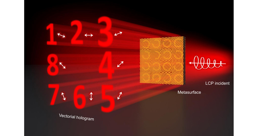
For the proof of concept, two functional THz polarization elements were realized using the tri-layer metasurface. A THz polarization analyzer was experimentally demonstrated that can give the direction of polarization of the incident wave by detecting the output image distribution. The distribution of the measured pattern indicates the polarization angle of the incident wave. The detected THz field was changed along with the incident polarization state. Another proposed metasurface device can generate a complex THz vectorial field under circularly polarized incident waves, as illustrated in Fig. 1. The transmitted field had eight channels with different polarizations. The holograms, which are numbers from 1 to 8, were generated at different positions on the detected plane. By choosing the polarization state to be detected, different images can be observed and a specific channel can be hidden. The designed metasurface devices work at 0.75 THz in the transmission mode with an efficiency of approximately 40%.
Figure 1.Schematic of the designed vectorial hologram metasurface device. Different holograms in eight polarization channels can be generated when the circularly polarized THz wave impinges on the metasurface, because the phase and polarization of the transmitted THz wave can be individually modulated. The hologram in a channel can be hidden by choosing the corresponding detected polarization state.
The designed metasurface has a tri-layer structure, as shown in Fig. 2(a). It consists of three layers of metallic structure and two space layers. The whole metasurface is fabricated on a 500-μm-thick high-resistance silicon freestanding substrate. The top and bottom layers are orthogonal metallic metagrating arrays that serve as polarization filters. The THz wave is incident through the top layer. The middle layer consists of a C-shaped split-ring antenna array, which is used to modulate the phase of the transmitted wave. The layers are made of the dielectric material polyimide (PI). All of these layers form a complex optical resonant cavity to achieve high working efficiency in transmission mode. The multi-layer transmitted metasurface has been demonstrated to have a high working efficiency of 70%–90%, which can be attributed to the Fabri–Porit like effect55-56 (see Section 1 of the Supplementary information for more details). Constructive interference can be produced at the designed frequency by tuning the length of the resonant cavity. The parameters of the designed metasurface were optimized using the commercial software FDTD solutions to model the structure. The working frequency was chosen as 0.75 THz with a corresponding wavelength of 400 μm. The size of each cell was optimized as 100 μm. The thicknesses of the PI layers and the three metallic layers were 40 μm and 150 nm, respectively. The top views of the top and bottom grating layers are shown inFig. 2(b) and2(d). The gratings of the top and bottom layers have the same width of 10 μm and period of 20 μm, but different directions. The angles between the x-axis and the directions of the top-layer and bottom-layer gratings are θ and θ+90°, respectively. When a circularly polarized THz wave is incident on the cell, the top-layer grating filters out the linearly polarized component with a polarization angle of θ+90°, and the C-shaped antenna array scatters the component that is cross-polarized with angle θ. Then, the bottom-layer grating filters out the wave with θ polarization.Figure 2(c) presents the top view of the C-shaped antenna in the middle metallic layer of the designed metasurface. The split-ring antenna array transfers the incident linear polarized wave to its cross-polarized state with an extra phase18,25. The outer and inner radii of the C-shaped antenna are r and R, which are optimized to 45 μm and 35 μm, respectively. The symmetric axis of the C-shaped antenna has an angle of θ+45° with respect to the x-axis, so the antenna can work with any linearly polarized incident wave. The opening angle of the C-shaped antenna is 2α, which can be tuned to modulate the phase of the transmitted wave. The Jones matrix of the unit cell of the designed metasurface can be expressed as: (see Section 2 of the Supplementary information)
Figure 2.Schematic and characteristics of the designed unit cell. (a) Concept of the designed tri-layer metasurface. The unit cell consists of three metal structure layers and two polyimide (PI) space layers. The top and bottom metallic layers are metagratings, and the middle metallic layer is a C-shaped split-ring antenna array. The thickness of the PI layers is 40 μm, and the thickness of the metal structure layers is 150 nm. (b–d) Top views of the top, middle, and bottom metal layers of the unit. The period of the structure P is 100 μm; θ andθ–90° are the angles between the metagrating direction and x-axis for the top and bottom layers, respectively; θ+45° is the angle between the symmetric axis of the C-shaped antenna and x-axis; 2α is the opening angle of the antenna; w and d are the width and period of the metagrating, which are 10 μm and 20 μm, respectively; r and R are the inner and outer radii of the antenna, which are 35 μm and 45 μm, respectively. (e) Transmitted spectrum of the metasurface with θ = 90°. The incident wave is x-polarized, and the transmitted light is y-polarized. (f) Amplitude and phase modulation of the eight selected antennas at 0.75 THz. Antennas 1 to 4 have opening angles 2α = 130, 96, 50, and 14°, and the angle between the symmetric axis and x-axis is –45°. Antennas 5 to 8 have the same opening angle as the first four antennas with a symmetric axis at 45°.
where θ is the angle between the x-axis and the direction of the top layer of the unit cell, and txy and φxy are the amplitude transmission and phase modulation of the y-polarized output when the incident wave is x-polarized. The phase modulation φxy(α) is a function of the opening angle 2α of the C-shaped antenna. One can see that the polarization state and phase of the output field are independent of each other. That is, the polarization state and the phase of the transmitted wave can be modulated individually by changing the angles θ and α.
Figure 2(e) shows the simulated amplitude transmission spectrum txy of the periodic identical unit cell of the metasurface. In the simulation, the THz wave was incident through the top layer. The angle θ of the unit cell was set as 90° so that the device could transfer the incident x-polarized wave into its cross-polarized partner, which was y-polarized, with high efficiency. As shown by the blue dashed curve, the transmission of the output y-polarized wave reached 0.8 at the designed working frequency of 0.75 THz. The transmission of the output x-polarized wave, which has the same polarization as the incident wave, was below 0.01, as shown by the green dashed line. The corresponding experimental results were measured using a home-built THz focal-plane imaging system57 (the measurement and evaluation methods are in Section 3 of the Supplementary information). The value of txy was over 0.7 in the frequency range of 0.4–1.1 THz and reached 0.8 at the central frequency of 0.75 THz. The identically polarized part txx remained about 0.05 in the experiment, which was mainly due to the inaccuracy of the measured incident polarization. Full-phase modulation of the transmitted cross-polarized wave was realized using eight C-shaped antennas whose phase modulations ranged from 0 to 2π with a step of π/8 while the amplitude transmission was maintained as 0.8.Figure 2(f) shows the amplitude and phase modulation of the selected antennas at the working frequency of 0.75 THz. The angle θ was set as 0. Antennas 1 to 4 had opening angles (2α) of 130, 96, 50, and 14°, and the angle between the symmetric axis of the antennas and the x-axis was –45°. Antennas 5 to 8 had the same opening angle as the first four antennas, while the angle between the symmetric axis of the antennas and the x-axis was 45°. The unit cells of the metasurface were built using combinations of these eight C-shaped antennas and metagratings with different directions.
THz metasurface polarization analyzer
A THz polarization analyzer was designed and fabricated using the proposed antennas. The metagratings of the top and bottom layers were designed as radial and azimuthal polarization filters, respectively. The C-shaped antenna array of the middle layer was designed as a lens (more details of the phase and polarization modulation of the device can be found in Section 4 of the Supplementary information). The designed metasurface device was fabricated with conventional UV lithography, thermal evaporation, and the lift-off technique. The fabricated device was a circular disc with a diameter of 1.5 cm containing 150 unit cells along the diameter. When a THz wave polarized with angle β is incident from the top layer, the designed device can generate a TEM01-mode spot with a rotation angle of β on the focal plane39,58. Thus, the polarization direction of the input wave can be distinguished by the distribution of the light pattern on the focal plane. The function of the device was verified experimentally. The setup is shown inFig. 3(a). A THz half-wave plate (THWP) whose fast axis has an angle of β/2 respect to the x-axis was used to generate a linearly polarized wave in the direction of angle β, and then the β-polarized wave passed through the metasurface device and generated a light spot on the focal plane. Measurements were carried out with four angles: β = 0, 45°, 90°, and 135°. The simulation results are shown inFig. 3(b1–b4). The fabricated metasurface device was measured with a THz focal-plane imaging system (see details in the Methods section). The results are shown inFig. 3(c1–c4). The white arrow represents the incident polarization state in all amplitude distribution images. The polarization angle of the incident wave can be distinguished clearly in the distribution of the focal spot, whose brightest part is along the β direction. For further verification of the function of the THz polarization analyzer, the amplitude distribution was extracted along the azimuthal direction of all results, as shown by the black dashed circle inFig. 3(b1).Figure 3(d1–d4) show the azimuthal amplitude distributions for β = 0, 45°, 90°, and 135°, respectively. The gray curves represent the amplitude distribution extracted from the simulated results while the red curves are from the experiments. The amplitude is normalized to the maximum amplitude in the case of β = 0. The maxima of the amplitude distribution correspond to 0, 45°, 90°, and 135°. The maximum absolute error in the experiment is 6.1° when β = 135°, and the average absolute error is below 3° for all experimental results, which is attributed to the non-uniformity of the incident THz waves. In contrast to a conventional polarizer, the designed metasurface polarization analyzer can provide the incident polarization angle via image analysis. The advantage of the proposed metasurface polarization analyzer is that it can work in single-shot detection. As it is well known, one needs to rotate the polarizer at least 180 degrees to obtain the polarization angle when a traditional polarization analyzer is used, which is inconvenient for measuring the polarization of a single pulse or transient field. This device can be used to characterize the incident polarization angle through a one-shot image with high accuracy.
Figure 3.Schematic and characteristics of the designed THz metasurface polarization analyzer. (a) Schematic of the working process of the THz metasurface polarization analyzer. An x-polarized THz wave is incident onto a THz half-wave plate (THWP), and the fast axis of the THWP is along the β/2 direction. The output THz wave is β-polarized and then incident on the metasurface device. The transmitted wave is transferred to the cross-polarization state, which is along the β–90° direction and focused on the focal plane. The amplitude distribution of the focal spot is along the θ direction. (b1–b4) Simulated amplitude distributions on the focal plane for β = 0, 45°, 90°, and 135°, respectively. Each white arrow represents the incident polarization state. (c1–c4) Experimental amplitude distributions on the focal plane for β = 0, 45°, 90°, and 135°, respectively. (d1)–(d4) Amplitude distribution curves extracted from the amplitude distributions along the black dashed circle in Fig. 3(b) for β = 0, 45°, 90°, and 135°, where the gray and red curves represent the simulated and experimental results, respectively.
On the basis of the designed units, a multi-channel THz vectorial hologram metasurface device was demonstrated experimentally. The device was designed with eight polarization channels, each of which can generate images of numbers 1–8 with different polarization states. The designed device consists of eight big cells named Channel 1 to Channel 8 (C1 to C8), whose alignment is shown in Fig. 4(a). Each big cell has 50×50 basic metasurface unit cells, which means the total area of the device is 1.5×1.5 cm2. The polarization state of a wave transmitted from C1 to C8 is designed to increase from 0 to 157.5° with a step of 22.5°, which equals to the respective angle θ of each channel. The phase modulations of C1 to C8 are designed to generate holograms of numbers 1 to 8 using the simulated annealing algorithm based on the Rayleigh–Sommerfeld diffraction theory. The diffraction distance was set to 5 mm away from the device. The phase distribution on the object plane was obtained after 2500 iterations, as shown in Section 5 of the Supporting information. The aforementioned eight C-shaped antennas with different rotation angles were used for the eight polarization states. The 64 selected C-shaped antennas are shown inFig. 4(b). The rotation angle of the antennas was changed along the metagrating direction. The eight channels C1 to C8 were built using combinations of these 64 antennas with the corresponding metagrating layers. The phases and polarization modulations of the channels are shown inFig. 4(c). The bars show the phase modulation of the corresponding cross-polarized wave. All the phase modulations range from 0 to 360° when the angle θ is changing. The blue dashed curves through the red stars represent the amplitude modulations of the 64 selected cells, which are between 0.74 and 0.88. This indicates that the designed device has a high working efficiency. The selected cells are aligned as the designed sequence and form the final device. A microscope image of part of the fabricated device is shown inFig. 4(d).Figure 4(e–g) show the images of the top, middle, and bottom layers of the structure in the white dashed frame. Although there are ghost images of other layers, one can see the metagrating and the C-shaped antennas are fabricated well.
Figure 4.Schematic of a vectorial hologram device. (a) Arrangement of the vectorial hologram device. The white arrow represents the polarization of the output wave through each big cell. (b) Schematic of the selected 64 C-shaped antennas, where 2α is the opening angle of the antennas, and θ represents the polarization angle of the output wave. (c) Amplitude and phase modulation of the transmitted cross-polarized wave for the 64 selected cells. The bars represent the phase modulation, and the blue dashed curves through the red stars represent the amplitude modulation. (d) Top-view microscope image of part of the fabricated device, where the white bar represents 500 μm. (e–g) Top-view microscope images of the top, middle, and bottom device layers, respectively. The white bar represents 50 μm.
The designed THz vectorial hologram device can be used to hide an image by choosing the polarization state to be detected. The image hiding was demonstrated experimentally. The working frequency was 0.75 THz. The incident x-polarized wave passed through a THz quarter-wave plate and generated a THz left-circularly polarized wave, which impinged on the metasurface device. The observed plane was 1.5 mm away from the device. The THz focal imaging system enabled recording of the complex amplitude of the transmitted THz wave. The experimental results are shown in Fig. 5. First, the image was measured with no polarization selected for detection. The images in all channels C1 to C8 could be distinguished clearly with almost the same amplitude, as shown inFig. 5(a). The white arrows indicate the polarization of each channel. The working efficiency was derived as the amplitude integral of the transmitted wave divided by the amplitude integral of the incident LCP THz wave, which was 0.39 in the experiment. The working efficiency is almost half of that of the basic cell, which can be attributed to that the top-layer meta-grating reflects the half electric field of the circularly polarized incident light. The deviation of the experimental efficiency from the simulated results consists of two parts. One is the loss in the hologram design, and the other is due to the experimental system (see Section 6 of the Supplementary information).Figure 5(b–i) show the results when the images of C1 to C8 are hidden, respectively. For the measurements inFig. 5(b–i), the polarizations chosen for detection were 67.5°, 90°, 112.5°, 135°, 157.5°, 0°, 22.5°, and 45°, respectively. The numbers 1 to 8 in C1 to C8 are hidden, while the images in other channels can still be observed with different amplitudes. The amplitude of each channel can be expressed as:
Figure 5.Experimental results for the image-hiding device. (a) Amplitude distribution of a hologram with no polarization state selected for detection. (b–i) Amplitude distributions when an image is hidden in channels C1 to C8, respectively, with the detected polarizations chosen as 67.5°, 90°, 112.5°, 135°, 157.5°, 0°, 22.5°, and 45°, respectively. Each white arrow represents the designed polarization state of the corresponding channel.
where EdCi indicates the detected electric field in Ci, ECi represents the generated electric field in Ciwhen no polarization is selected for detection, θi is the designed polarization angle of Ci, and θd is the detected polarization angle. Figure 6 shows the normalized amplitude for each detected polarization in each channel. The colored curves are extracted fromFig. 5(b–i) and correspond to channels C1 to C8 when each is hidden. Each red arrow represents the designed polarization state of the hidden channel. The amplitude of the hidden image is about 0.1, while the amplitude trends of all channels agree well withEq. (2). The deviation can be attributed to fabrication errors such as the thickness error of the PI layer, which results in the phase deviation of the transmitted wave.
Figure 6.Experimental amplitudes for the image-hiding device. The colored curves are extracted from Fig. 5(b–i) with the detected polarization states being 67.5°, 90°, 112.5°, 135°, 157.5°, 0°, 22.5°, and 45°, respectively. Each red arrow represents the designed polarization state of the hidden channel.
In conclusion, a device was designed that can generate a THz vectorial beam using a tri-layer metasurface. The phase and polarization of the transmitted wave can be modulated individually at the same time by tuning the geometric parameters of the tri-layer metasurface. Two THz vectorial devices were demonstrated experimentally. One is a THz polarization analyzer that has a phase-distributed lens and azimuthally polarized modulation. Under linearly polarized illumination, the distribution of the focal spot is along the polarization angle of the incident wave, so the polarization angle of the incident wave can be obtained accurately and clearly. Moreover, an eight-channel THz vectorial hologram device was realized that can hide the information in a specific channel via selection of the polarization state to be detected. The images of numbers 1 to 8 were loaded into channels C1 to C8, and the detected polarization angle was varied among 67.5, 90, 112.5, 135, 157.5, 0, 22.5, and 45°. The corresponding numbers 1 to 8 were hidden with a high efficiency of 0.79 in the experiment. Overall, this is an efficient, new method to manipulate a vectorial field using a tri-layer metasurface, which is especially suitable for THz waves. Although the designed metasurface just generated a linear polarization distribution in the far-field, it can be used for arbitrary polarization manipulation. By rotating the C-shaped antenna in the middle layer, nearly continuous amplitude modulation of the transmitted wave can be obtained. In the other word, the individual modulation of the amplitude, phase, and polarization state can be achieved based on the proposed tri-layer metasurface, thus two far fields with arbitrary amplitude and phase distribution for x- and y-polarization can be constructed. The superposition of these two fields with x- and y-polarized will generate an arbitrary polarized field in the far-field. This method can also be extended to other wavebands and adapted for more functions.
Methods
Fabrication of the designed metasurface devices
The designed metasurface devices were fabricated with conventional UV lithography, thermal evaporation, and the lift-off technique. Regular lithography was first carried out, and then lift-off was performed to obtain the bottom-layer metal metagrating on a 500-μm-thick high-resistance silicon substrate. The PI was then spin-coated on the metagrating four times. After each spin-coating, gradient baking of the sample was done to turn the PI into a solid, and an exact 10-μm-thick PI sample was obtained. After four rounds of coating and baking, a 40-μm-thick PI spacer was obtained. Then, regular lithography and lift-off were again done to obtain the metal split-ring antenna array of the middle layer with highly precise alignment with the bottom layer metagrating. Then, the coating and baking were repeated to obtain another 40-μm-thick PI spacer on the metal split-ring antenna array. Finally, regular lithography and lift-off were done to obtain the top layer of the metal metagrating.
Experimental setup
A THz focal-plane imaging system was used to characterize the performance of the designed devices. A laser beam with a central wavelength of 800 nm and average power of 900 mW was divided into two parts, which were used as the pump (880 mW) and probe (20 mW) beams for generating and detecting THz waves, respectively. The pump beam impinged on a 1-mm-thick <110> ZnTe crystal to generate the THz beam via optical rectification. The horizontally polarized ( x-polarized) THz beam (with a diameter of 15 mm) passed through a THz polarizer to maintain its polarization, then passed through a THz quarter-wave plate to generate left-circularly polarized light at a working frequency of 0.75 THz, and then impinged on the structure. The scattered THz beam was detected using another <110> ZnTe crystal. The THz complex field was extracted using balanced electro-optic detection.
References
[1] Zhang XC, Xu JZ. Introduction to THz Wave Photonics (Springer, New York, 2010).
Huan Zhao, Xinke Wang, Shutian Liu, Yan Zhang. Highly efficient vectorial field manipulation using a transmitted tri-layer metasurface in the terahertz band[J]. Opto-Electronic Advances, 2023, 6(2): 220012