
Che-Hsuan Huang, Yu-Tang Cheng, Yung-Chi Tsao, Xinke Liu, Hao-Chung Kuo, "Micro-LED backlight module by deep reinforcement learning and micro-macro-hybrid environment control agent," Photonics Res. 10, 269 (2022)
- Photonics Research
- Vol. 10, Issue 2, 269 (2022)
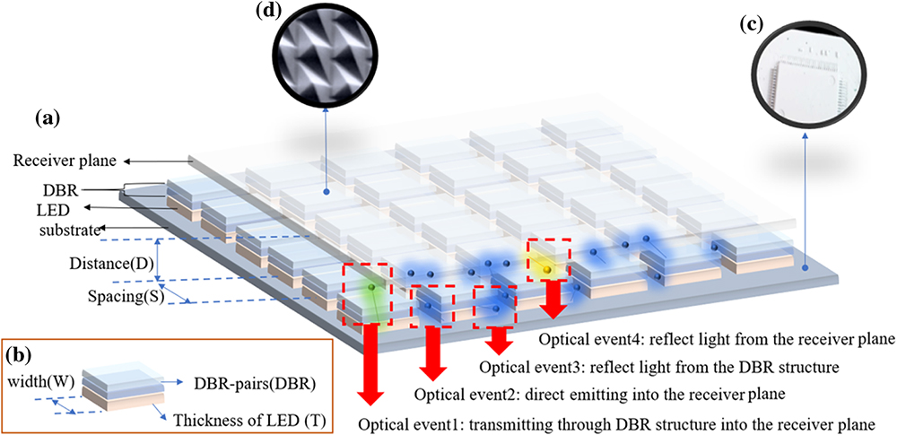
Fig. 1. (a) Schematic diagram of micro-LED backlight module; (b) schematic diagram of LED with DBR structure; (c) highly-reflective surface substrate; (d) etching structure of the receiver.
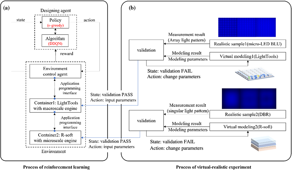
Fig. 2. Workflow for optimizing micro-LED backlight module: (a) the process of deep reinforcement learning and (b) the process of the virtual-realistic experiment.
Fig. 3. (a) Workflow of environment control agent and schematic diagram of the virtual-realistic experiment; (b) principle of kernel1: Gaussian and Lambertian reflection; (c) principle of kernel2: BSDF properties.
Fig. 4. Workflow of DDQN network.
Fig. 5. Virtual-realistic experiment: (a) single light pattern analysis; (b) module pattern analysis.
Fig. 6. Result of reinforcement learning: (a) uniformity for every iteration with reward function1; (b) uniformity for every iteration with reward function2; (c) uniformity for every iteration with reward function3; (d) the best result by reward function1; (e) the best result by reward function2; (f) the best result by reward function3.
Fig. 7. Demonstration of the micro-LED backlight module.
Fig. 8. Influence of DBR structure: (a) light pattern with state S b 3 ′ S b 3 S b 3 S b 3 ′
Fig. 9. Schematic of resonant loss for the micro-LED backlight module.
|
Table 1. Definition List of Action
|
Table 2. Definition List of State
|
Table 3. Definition List for Range of Parameters
|
Table 4. Results of Virtual-Realistic Experiment
|
Table 5. Best Uniformity for Different Reward Functions
|
Table 6. Work Efficiency of Designing Agent


Set citation alerts for the article
Please enter your email address

© Copyright 2018-2021 | Chinese Laser Press. All Rights Reserved 沪ICP备15018463号-20