• Photonics Research
  • Vol. 10, Issue 7, 1669 (2022)
Yaqing Jin1、2, Ye Yang3、4, Huibo Hong1、2, Xiao Xiang1、2, Runai Quan1、2, Tao Liu1、2, Shougang Zhang1、2, Ninghua Zhu3、5、6, Ming Li3、5、6、7, and Ruifang Dong1、2、*
Author Affiliations
  • 1Key Laboratory of Time and Frequency Primary Standards, National Time Service Center, Chinese Academy of Sciences, Xi’an 710600, China
  • 2School of Astronomy and Space Science, University of Chinese Academy of Sciences, Beijing 100049, China
  • 3State Key Laboratory on Integrated Optoelectronics, Institute of Semiconductors, Chinese Academy of Sciences, Beijing 100083, China
  • 4The 29th Research Institute of China Electronics Technology Group Corporation, Chengdu 610029, China
  • 5School of Electronic, Electrical and Communication Engineering, University of Chinese Academy of Sciences, Beijing 100049, China
  • 6Center of Materials Science and Optoelectronics Engineering, University of Chinese Academy of Sciences, Beijing 100190, China
  • 7e-mail: ml@semi.ac.cn
  • show less
    DOI: 10.1364/PRJ.453934 Cite this Article Set citation alerts
    Yaqing Jin, Ye Yang, Huibo Hong, Xiao Xiang, Runai Quan, Tao Liu, Shougang Zhang, Ninghua Zhu, Ming Li, Ruifang Dong. Quantum microwave photonics in radio-over-fiber systems[J]. Photonics Research, 2022, 10(7): 1669 Copy Citation Text show less
    Principal diagrams of the classical and quantum MWP in the RoF link. (a) depicts the acquired RF from the classical broadband optical pulse. For the quantum MWP with time-energy entangled biphoton source, (b) depicts the nonlocally acquired RF from the heralded signal photons, and (c) depicts the RF distillation from dispersion distortion from the heralded idler photons.
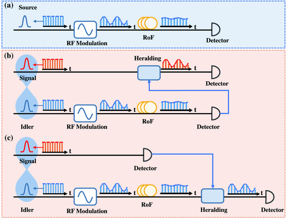
    Fig. 1. Principal diagrams of the classical and quantum MWP in the RoF link. (a) depicts the acquired RF from the classical broadband optical pulse. For the quantum MWP with time-energy entangled biphoton source, (b) depicts the nonlocally acquired RF from the heralded signal photons, and (c) depicts the RF distillation from dispersion distortion from the heralded idler photons.
    Experimental setup of the QMWP in a simulated RoF link. (a) depicts the setup for the generation of the utilized time-energy entangled biphoton source, and (b) plots the RoF link. The idler photons of the time-energy entangled biphoton source are modulated by a high-speed RF signal (ωRF) via the EOM and then transmitted through the DCM to simulate the RoF. (c) shows the setup for measurement and nonlocal recovery of the RF signal based on the QMWP method. The SNSPDs D1 and D2 are used to detect the arrived signal and idler photons. The TCSPC in the TTTR mode is used to record the time arrivals of the SNSPDs, and its sync input shares the same 10 MHz time base with the RF signal. The time differences between the individually recorded photon events and the relevant last sync event measure the photon waveforms over time. Based on the auxiliary cross-correlation searching program, the coincidence between the recorded signal and the idler photon events is acquired and used for the post-selection. The inset of (c) plots the direct and coincidence-assisted measurement of the signal photon waveforms.
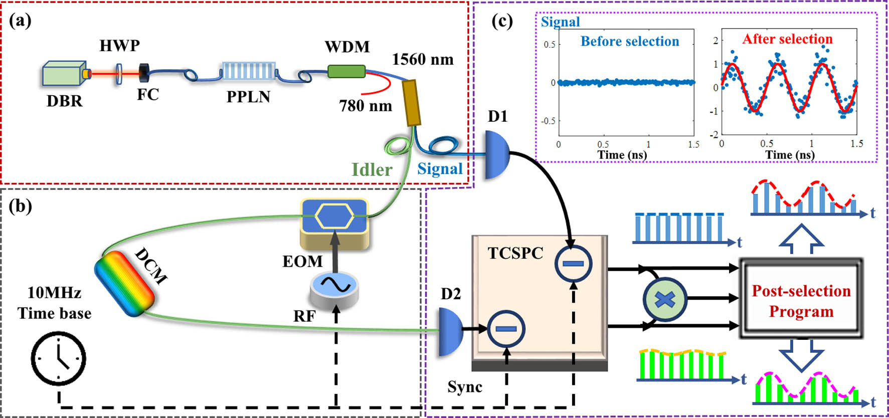
    Fig. 2. Experimental setup of the QMWP in a simulated RoF link. (a) depicts the setup for the generation of the utilized time-energy entangled biphoton source, and (b) plots the RoF link. The idler photons of the time-energy entangled biphoton source are modulated by a high-speed RF signal (ωRF) via the EOM and then transmitted through the DCM to simulate the RoF. (c) shows the setup for measurement and nonlocal recovery of the RF signal based on the QMWP method. The SNSPDs D1 and D2 are used to detect the arrived signal and idler photons. The TCSPC in the TTTR mode is used to record the time arrivals of the SNSPDs, and its sync input shares the same 10 MHz time base with the RF signal. The time differences between the individually recorded photon events and the relevant last sync event measure the photon waveforms over time. Based on the auxiliary cross-correlation searching program, the coincidence between the recorded signal and the idler photon events is acquired and used for the post-selection. The inset of (c) plots the direct and coincidence-assisted measurement of the signal photon waveforms.
    Experimental results of the nonlocal mapping of the RF signal based on the QMWP scheme, in which the RF signal is set as 2 GHz with a modulation power of 10 dBm, and no DCM is put in the setup. (a) The measured signal (blue) and idler (green) photon waveforms over time based on the direct detection. (b) The DFT spectra of the signal (blue) and idler (green) photon waveforms. (c) The acquired coincidence histogram between the signal and idler photons. Under the conditions that the heralding window is far from (I) and at the center of (II) the coincidence histogram, the reconstructed photon waveforms after the post-selection are respectively plotted in (d) and (e). It can be seen that only the signal photons post-selected from the coincidence histogram can output the RF-modulated periodic waveform. The power spectra of the measured signal photon waveforms before (blue) and after (red) the post-selection are shown in (f).
    Fig. 3. Experimental results of the nonlocal mapping of the RF signal based on the QMWP scheme, in which the RF signal is set as 2 GHz with a modulation power of 10 dBm, and no DCM is put in the setup. (a) The measured signal (blue) and idler (green) photon waveforms over time based on the direct detection. (b) The DFT spectra of the signal (blue) and idler (green) photon waveforms. (c) The acquired coincidence histogram between the signal and idler photons. Under the conditions that the heralding window is far from (I) and at the center of (II) the coincidence histogram, the reconstructed photon waveforms after the post-selection are respectively plotted in (d) and (e). It can be seen that only the signal photons post-selected from the coincidence histogram can output the RF-modulated periodic waveform. The power spectra of the measured signal photon waveforms before (blue) and after (red) the post-selection are shown in (f).
    DFT spectra of (a) the directly measured idler photon waveforms, (c) the post-selected signal photon waveforms, and (e) the post-selected idler photon waveforms. Different RF modulation powers are applied for comparing the SFDR regarding the direct detection and post-selected results. The 2 GHz RF signal and noise powers for the fundamental and second harmonic components at different modulation powers are plotted in (b), (d), and (f). By applying linear fitting to these measurements in (b), (d), and (f), the SFDR of the system can be extrapolated.
    Fig. 4. DFT spectra of (a) the directly measured idler photon waveforms, (c) the post-selected signal photon waveforms, and (e) the post-selected idler photon waveforms. Different RF modulation powers are applied for comparing the SFDR regarding the direct detection and post-selected results. The 2 GHz RF signal and noise powers for the fundamental and second harmonic components at different modulation powers are plotted in (b), (d), and (f). By applying linear fitting to these measurements in (b), (d), and (f), the SFDR of the system can be extrapolated.
    Experimental results of the nonlocal mapping of the RoF signal based on the QMWP scheme, in which the RF is set at 2 GHz with a modulation power of 10 dBm, and the utilized DCM has a dispersion of 495 ps/nm. (a) The measured signal (blue) and idler (green) photon waveforms are based on direct detection. (b) The power spectra of the signal (blue) and idler (green) photon waveforms. (c) The reconstructed signal photon waveforms after the post-selections are applied. (d) The power spectra of the measured signal photon waveforms (red) after the post-selection. (e) The recovered RF signal SNR plot as a function of the heralding time window width, which shows a maximum when the heralding window width is equal to the FWHM of the measured coincidence. (f) The plot of the recovered RF signal SNR as a function of the dispersion.
    Fig. 5. Experimental results of the nonlocal mapping of the RoF signal based on the QMWP scheme, in which the RF is set at 2 GHz with a modulation power of 10 dBm, and the utilized DCM has a dispersion of 495 ps/nm. (a) The measured signal (blue) and idler (green) photon waveforms are based on direct detection. (b) The power spectra of the signal (blue) and idler (green) photon waveforms. (c) The reconstructed signal photon waveforms after the post-selections are applied. (d) The power spectra of the measured signal photon waveforms (red) after the post-selection. (e) The recovered RF signal SNR plot as a function of the heralding time window width, which shows a maximum when the heralding window width is equal to the FWHM of the measured coincidence. (f) The plot of the recovered RF signal SNR as a function of the dispersion.
    Experimental results of the distilled RoF signal based on the QMWP scheme, in which the RF signal is set as 2 GHz with a modulation power of 10 dBm, and the utilized DCM has a dispersion of 495 ps/nm. (a) The measured idler photon waveform and (b) power spectra after the post-selection. (c) The plot of the distilled RF signal SNR as a function of the heralding time window width, which shows a maximum when the heralding window width is at 0.18 ns. (d) The plot of the RF signal SNR and the corresponding post-selected idler photon number as a function of the dispersion.
    Fig. 6. Experimental results of the distilled RoF signal based on the QMWP scheme, in which the RF signal is set as 2 GHz with a modulation power of 10 dBm, and the utilized DCM has a dispersion of 495 ps/nm. (a) The measured idler photon waveform and (b) power spectra after the post-selection. (c) The plot of the distilled RF signal SNR as a function of the heralding time window width, which shows a maximum when the heralding window width is at 0.18 ns. (d) The plot of the RF signal SNR and the corresponding post-selected idler photon number as a function of the dispersion.
    Yaqing Jin, Ye Yang, Huibo Hong, Xiao Xiang, Runai Quan, Tao Liu, Shougang Zhang, Ninghua Zhu, Ming Li, Ruifang Dong. Quantum microwave photonics in radio-over-fiber systems[J]. Photonics Research, 2022, 10(7): 1669
    Download Citation