
Yaqing Jin, Ye Yang, Huibo Hong, Xiao Xiang, Runai Quan, Tao Liu, Shougang Zhang, Ninghua Zhu, Ming Li, Ruifang Dong, "Quantum microwave photonics in radio-over-fiber systems," Photonics Res. 10, 1669 (2022)
- Photonics Research
- Vol. 10, Issue 7, 1669 (2022)
Abstract
1. INTRODUCTION
Microwave photonics (MWP), which uses photonic techniques to deal with microwave signals, has extended to numerous applications covering broadband wireless access networks, sensor networks, radar, satellite communications, and warfare systems [1,2]. At the same time, the bottlenecks of the MWP have also emerged, which place restrictions on its usability. For example, as the main branch of MWP, radio-over-fiber (RoF) uses optical fibers for transmitting microwave signals to a distant receiver. RoF benefits from the advantages of high bandwidth and low loss of optical fibers and shows excellent performance on high speed and long-distance propagation [3–6]. To meet the rapidly increasing demand for high capacity, broadband optical pulses are widely used as the optical carrier together with the method of wavelength division multiplexing (WDM) [1,7]. However, due to the large spectral width, the transmitted microwave signal is severely influenced by the fiber chromatic dispersion. In addition, suppression of the electrical distortion from harmonic and intermodulation is also crucial for the performance of MWP.
Over the past decades, quantum correlations between photon pairs have provided diversified access to surpass classical capabilities in various applications, including communication, simulation, computation, and military field [8–13]. For instance, by using the spatial correlation between the photon pairs, the quantum imaging system [14–16] enables the nonlocal obtaining of the image information of the object that is hardly reachable via direct detection with the fewest number of photons and sub-diffraction resolution [17]. With these virtues, quantum imaging has been extensively developed [18–21] and extended to abundant applications such as quantum-secured imaging [22], quantum illumination [23], and wide-field microscope [24]. The temporal correlation between the photon pairs has also been effectively applied in quantum clock synchronization [25–28], quantum key distribution [29–32], and quantum spectroscopy [33,34]. Recently, nonlocal temporal shaping of the photons has been proposed [35,36]. Therefore, it is expected to realize the nonlocal RF modulation and quantum enhancement in MWP technology.
This paper reports a quantum microwave photonics (QMWP) scheme in the RoF system with the time-energy entangled biphoton source as the optical carrier. Based on this scheme, the radio frequency (RF) modulation on the idler photons can be nonlocally mapped onto the signal photons with an improved spurious-free dynamic range (SFDR) in terms of second harmonic distortion and strong resistance to dispersion impact associated with the ultrashort pulse carrier. Furthermore, by applying coincidence-based selection to the idler photons, SFDR improvement of the direct RF modulation and anti-dispersion capability of the RoF signal can be achieved. Combined with the advantages of ultra-weak detection and high-speed processing rendered by the single-photon MWP (SP-MWP) [37] method, the QMWP provides unprecedented possibilities for MWP technology.
2. PRINCIPLE MODEL
A basic comparison between the classical MWP and QMWP schemes in RoF systems is first presented. Without including the optical signal processor, the schematic diagram of the RoF system based on the classical MWP is depicted in Fig. 1(a). With a broadband optical source as the optical carrier, due to the frequency dependence of the fiber dispersion, the microwave signal carried by different optical frequency components will suffer different phase variations. Eventually, the recovered RF signal from the optical carrier will be severely influenced and even covered. In comparison, when a time-energy entangled biphoton source is used as the carrier, the RoF system based on the QMWP method is depicted in Figs. 1(b) and 1(c). Due to the time-energy entanglement between the signal and idler photons, any time/frequency-related manipulation onto the idler photons will be nonlocally mapped onto their relevant signal photons. Since the RF modulation on the idler photons can be treated as the temporal shaping of the photon flows, such shaping should be nonlocally mapped onto their “twin” signal photons due to the entanglement [35,36]. The function of heralding is to find out the “twin” signal photons to the idler photons, and thus the heralded signal photons will present the corresponding temporal shaping. At the same time, the fiber dispersion in the idler path does not affect the nonlocal temporal shaping but broadens the time window of finding out the “twin” signal photons to the idler photons. Therefore, the recovered RF modulation from the signal photons has strong resistance to the dispersion [Fig. 1(b)]. As the heralding can also help to identify the idler photons, which suffer less dispersion effect, the recovery of the RF signal can be built based on the appropriately heralded idler photons, thus showing a certain degree of resilience to dispersion [Fig. 1(c)]. The theoretical analysis is deduced in the following paragraph.
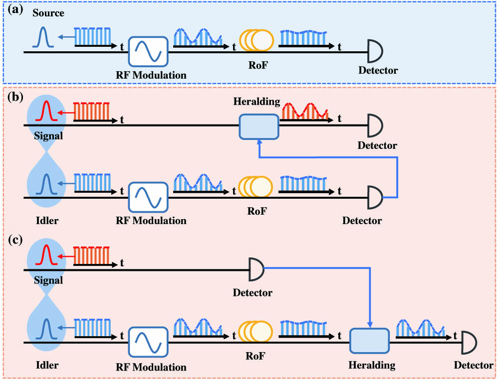
Figure 1.Principal diagrams of the classical and quantum MWP in the RoF link. (a) depicts the acquired RF from the classical broadband optical pulse. For the quantum MWP with time-energy entangled biphoton source, (b) depicts the nonlocally acquired RF from the heralded signal photons, and (c) depicts the RF distillation from dispersion distortion from the heralded idler photons.
Assuming the pulse source has a Fourier-transform-limited Gaussian shape for simplicity, its temporal amplitude function can be written as
To evaluate the propagation characteristic of the RF-modulated broadband optical signal through fiber, the Fourier transformation is applied to Eq. (3) to give the spectral wave function as
The transfer function of the fiber is given by
Its temporal amplitude function is derived by the inverse Fourier transformation of
As seen from Eq. (7), the fiber dispersion leads to the pulse duration broadening and introduces different phase and temporal shifts to the two modulation-associated terms. The different phase shifts give rise to the well-known frequency-dependent fading of the RF modulation [1], while the different temporal shifts introduce a more severe dispersion distortion to the transmitted RF signal.
For the QMWP in the RoF link [Figs. 1(b) and 1(c)]. According to quantum theory, the temporal wave function of the time-energy entangled biphoton source can be given by
When the RF signal with
Under the condition that the idler photons are subsequently traveled through the long-distance optical fiber, whose transfer function is given by Eq. (4), the temporal wave function of the two-photon state after the modulation and dispersion can then be given by
One can notice that Eq. (10) is similar to Eq. (7) except that the evolution of
Here,
Here,
As depicted in Fig. 1(c), conditioned by the second-order Glauber correlation between the signal and idler photons, the heralding of the idler photons can also be operated. The temporal wave function of the heralded idler photons can be written as
We can see that Eq. (14) has a similar form to Eq. (12) except for a different factor of
3. EXPERIMENTAL SETUP
The experimental setup of the QMWP in the RoF link is shown in Fig. 2. Figure 2(a) depicts the setup for the generation of the utilized time-energy entangled biphoton source. Via the spontaneous parametric down-conversion process (SPDC), the time-energy entangled biphoton source at 1560 nm is generated from a 10-mm-long, type-II quasi-phase-matched periodically poled lithium niobate (PPLN, HC Photonics) waveguide with a period of 8.3 μm. The pump laser is a 780 nm DBR laser diode (Photodigm) with a linewidth of 2 MHz [40]. As the PPLN waveguide is integrated with the polarization-maintaining single-mode fiber (PM-SMF), the produced photon pairs can be directly coupled into the fiber channels. The residual pump can be effectively removed by inserting a customized WDM (PMFWDM-5678-222, Optizone) at the PPLN output. Afterward, the orthogonally polarized signal and idler photons are spatially separated by a fiber polarization beam splitter (FPBS) for subsequent utilization. The full-width at half-maximum (FWHM) single-photon spectral widths for both signal and idler were measured as about 2.4 nm [41]. Figure 2(b) shows the RoF link. On the idler photon path, intensity modulation is applied by employing an external Mach–Zehnder modulator (MZM, PowerBit F10-0, Oclaro). The modulator is driven by a sinusoidal RF signal from a signal generator (SG382, Stanford Research). The fiber-Bragg-grating-based dispersion compensation module (DCM, Proximion AB) is used to simulate the dispersion in long-distance fibers. In our experiment, different DCMs with group delay dispersion (GDD) values ranging from 165 to 826 ps/nm are applied. According to the given experimental parameters, the approximations required for deriving the expressions of Eqs. (13) and (14) can be readily satisfied. Figure 2(c) plots the setup for measurement of the RF signal based on the QMWP method, which utilizes the coincidence-based post-selection to verify the heralding.
![]()
Figure 2.Experimental setup of the QMWP in a simulated RoF link. (a) depicts the setup for the generation of the utilized time-energy entangled biphoton source, and (b) plots the RoF link. The idler photons of the time-energy entangled biphoton source are modulated by a high-speed RF signal (
In our experiment, the low-jitter superconductive nanowire single-photon detectors (SNSPDs, Photec) are used to detect the signal and idler photons, which have a time jitter of about 50 ps [42]. The two SNSPD outputs are then delivered to different input ports (CH1 and CH2) of the TCSPC module (PicoQuant Hydraharp 400), which is operated in the time tagged time-resolved (TTTR) T3 mode. In this mode, the TCSPC records the arrival times of the photon events for each input port, and the measurement time for the photon event recording is set as 180 s. The time-bin resolution of the TCSPC is 8 ps, corresponding to a sampling frequency of
4. EXPERIMENTAL RESULTS AND ANALYSIS
The nonlocal mapping of the RF modulation on the idler photons to the signal photons is first investigated without the DCM in the setup. By setting the RF signal at 2 GHz with a modulation power of 10 dBm, Fig. 3(a) depicts direct measurements of the signal (blue) and idler (green) photon waveforms over time. Note that the recorded idler photon counts in Fig. 3(a) are much lower than the signal photons due to the insertion loss by the intensity modulator. One can see the RF modulation from the trace of the idler photons, while that of the signal photons is clean from any modulation. Applying discrete Fourier transform (DFT) to the waveforms, the corresponding power spectra of the signal (blue) and idler (green) are given in Fig. 3(b). One notes that the DFT noise floor is
![]()
Figure 3.Experimental results of the nonlocal mapping of the RF signal based on the QMWP scheme, in which the RF signal is set as 2 GHz with a modulation power of 10 dBm, and no DCM is put in the setup. (a) The measured signal (blue) and idler (green) photon waveforms over time based on the direct detection. (b) The DFT spectra of the signal (blue) and idler (green) photon waveforms. (c) The acquired coincidence histogram between the signal and idler photons. Under the conditions that the heralding window is far from (I) and at the center of (II) the coincidence histogram, the reconstructed photon waveforms after the post-selection are respectively plotted in (d) and (e). It can be seen that only the signal photons post-selected from the coincidence histogram can output the RF-modulated periodic waveform. The power spectra of the measured signal photon waveforms before (blue) and after (red) the post-selection are shown in (f).
As shown in Fig. 3(c), the coincidence distribution between the signal and idler is found according to the cross-correlation program, which has an FWHM temporal width of 70 ps and is determined by the timing jitters of the SNSPDs. To manipulate the post-selection, the heralding window with a width of
By comparison between Figs. 3(b) and 3(f), the nonlocally acquired RF modulation exhibits apparent suppression of the second harmonic distortion. To prove this improvement, the DFT spectra of the directly measured idler photon waveforms [Fig. 4(a)], the post-selected signal photon waveforms [Fig. 4(c)], and the post-selected idler photon waveforms [Fig. 4(e)] are respectively plotted. Consider that the received power is determined by the number of photons detected. The corresponding photon counts in these plots remain the same to compare the signal and noise power at the same received power. Different RF modulation powers are applied to investigate the second harmonic distortion suppression. From Fig. 4(a) one can see distinct second harmonic distortion as the RF modulation power increases. Meanwhile, the photon spectra of the post-selected signal and idler photons are depicted in Figs. 4(c) and 4(e), and apparent suppression of the second harmonic distortion can be seen. In addition, the noise floor in Figs. 4(c) and 4(e) is 4.8 dB and 4.4 dB lower than that in Fig. 4(a), respectively, and the SNR of the post-selected photons is higher than that of the directly measured photons under the same photon counts. For example, when the RF modulation power is 9 dBm, the SNRs of the post-selected idler photons and signal photons are 7.9 dB and 7.7 dB, which are 3.8 dB and 3.6 dB higher than that of the unselected photon (4.1 dB). The 2 GHz RF signal and noise power for the fundamental and second harmonic components at different RF powers are plotted in Figs. 4(b), 4(d), and 4(f). In our experiment, the spectral resolution of the DFT is
![]()
Figure 4.DFT spectra of (a) the directly measured idler photon waveforms, (c) the post-selected signal photon waveforms, and (e) the post-selected idler photon waveforms. Different RF modulation powers are applied for comparing the SFDR regarding the direct detection and post-selected results. The 2 GHz RF signal and noise powers for the fundamental and second harmonic components at different modulation powers are plotted in (b), (d), and (f). By applying linear fitting to these measurements in (b), (d), and (f), the SFDR of the system can be extrapolated.
Next, we test the resistance to the dispersion distortion by the QMWP system with the DCM in the setup. By setting the RF modulation at 2 GHz with a modulation power of 10 dBm and using the DCM with a dispersion of 495 ps/nm, the directly measured photon waveforms of the signal (blue dots) and idler (green dots) photons are presented in Fig. 5(a). Their corresponding spectra are plotted in Fig. 5(b). Due to the dispersion, the RF modulation on the idler cannot be detected. However, this bottleneck in the RoF can be overcome with the QMWP method. We recover the RF modulation both on the signal and idler photons by applying the coincidence-based post-selection. By choosing the heralding time window width as the FWHM coincidence width (1.3 ns), the post-selected signal photon waveform is shown in Fig. 5(c) by red dots, and the red curve in Fig. 5(d) gives its spectrum, which presents an SNR of 6.3 dB. The results show that the nonlocally acquired RF signal from the post-selected signal photons can be immune from the dispersion distortion associated with the ultrashort pulse carrier. Figure 5(e) further presents the achieved SNR as a function of the heralding time window width, which shows the optimum SNR at the FWHM of the measured coincidence. By varying the dispersion from 165 to 826 ps/nm, we study the heralding width for the optimized SNR, which is always the FWHM of the measured coincidence. This anti-dispersion property is further tested by varying the dispersion from 165 to 826 ps/nm. The heralding width for optimized SNR is always the FWHM of the measured coincidence, and the SNR of the recovered RF with the varying dispersion is shown in Fig. 5(f) by red stars. Compared with the relevant photon counts after post selection, which are also shown in Fig. 5(f) by the black curve, the degradation of the SNR agrees well with the post-selected photon counts.
![]()
Figure 5.Experimental results of the nonlocal mapping of the RoF signal based on the QMWP scheme, in which the RF is set at 2 GHz with a modulation power of 10 dBm, and the utilized DCM has a dispersion of 495 ps/nm. (a) The measured signal (blue) and idler (green) photon waveforms are based on direct detection. (b) The power spectra of the signal (blue) and idler (green) photon waveforms. (c) The reconstructed signal photon waveforms after the post-selections are applied. (d) The power spectra of the measured signal photon waveforms (red) after the post-selection. (e) The recovered RF signal SNR plot as a function of the heralding time window width, which shows a maximum when the heralding window width is equal to the FWHM of the measured coincidence. (f) The plot of the recovered RF signal SNR as a function of the dispersion.
Further applying post-selection onto the idler photons, we have also demonstrated efficient suppression of the dispersion distortion onto the RF signal. Under the same RF modulation and dispersion condition as above, the distilled waveform from the post-selected idler photons (pink dots) is plotted in Fig. 6(a). The corresponding DFT spectra are shown in Fig. 6(b), which shows the successful acquisition of the 2 GHz RF signal from the post-selected idler photons with an SNR of 1.9 dB. The achievable SNR of the RF signal as a function of the heralding window width is plotted in Fig. 6(c), which shows the maximum SNR at 0.18 ns. The optimized heralding width for different dispersions, varying from 165 to 826 ps/nm, is also investigated, which remains almost constant at 0.18 ns. The achieved maximum SNR as a function of the dispersion is given in Fig. 6(d). Because the coincidence width increases with the growth of the GDD, the photon count in the heralding width decreases dramatically. However, similar to the results shown in Fig. 5(f), the degradation of the SNR coincides with the post-selected photon counts. Though the distilled RF signal from the idler photons has an SNR worse than that from the signal photons, it witnesses successful dispersion distortion suppression that cannot be overcome other than dispersion compensation. By increasing the photon counts, the SNR can be effectively improved.
![]()
Figure 6.Experimental results of the distilled RoF signal based on the QMWP scheme, in which the RF signal is set as 2 GHz with a modulation power of 10 dBm, and the utilized DCM has a dispersion of 495 ps/nm. (a) The measured idler photon waveform and (b) power spectra after the post-selection. (c) The plot of the distilled RF signal SNR as a function of the heralding time window width, which shows a maximum when the heralding window width is at 0.18 ns. (d) The plot of the RF signal SNR and the corresponding post-selected idler photon number as a function of the dispersion.
5. CONCLUSIONS
In summary, we have proposed and demonstrated a proof-of-principle QMWP experiment. According to the demonstration, the QMWP technology not only inherits all the advantages of the SP-MWP [37] but also shows valuable superiority over the classical MWP. First, the QMWP can realize the nonlocal acquisition of the RF signal from the unmodulated optical carrier. The recovered RF signal exhibits significantly improved SFDR concerning the second harmonic distortion and excellent resistance to the dispersion distortion associated with ultrashort pulse carriers. Furthermore, the QMWP provides the capability of improving the SFDR of the RF signal on the directly modulated photon carrier and effectively distilling the RF signal from the dispersion distortion. These advantages will open numerous new possibilities in modern communication and networks, such as encrypted processing in communication and radar application.
Acknowledgment
Acknowledgment. We thank Si Shen and Hao Yu for their useful discussions.
References
[1] C. H. Lee. Microwave Photonics(2006).
[2] K. Xu, R. Wang, Y. Dai, F. Yin, J. Li, Y. Ji, J. Lin. Microwave photonics: radio-over-fiber links, systems, and applications. Photon. Res., 2, B54-B63(2014).
[3] T. Kawanishi. THz and photonic seamless communications. J. Lightwave Technol., 37, 1671-1679(2019).
[4] Y. Yao, F. Zhang, Y. Zhang, X. Ye, D. Zhu, S. Pan. Demonstration of ultra-high-resolution photonics-based Ka-band inverse synthetic aperture radar imaging. Optical Fiber Communications Conference and Exposition (OFC), Th3G.5(2018).
[5] A. Malacarne, S. Maresca, F. Scotti, B. Hussain, L. Lembo, G. Serafino, A. Bogoni, P. Ghelfi. A ultrawide-band VCSEL-based radar-over-fiber system. International Topical Meeting on Microwave Photonics (MWP), 1-4(2019).
[6] C. Lim, A. Nirmalathas. Radio-over-fiber technology: present and future. J. Lightwave Technol., 39, 881-888(2021).
[7] T. Yamamoto, K. R. Tamura, M. Nakazawa. 1.28 Tbit/s—70-km OTDM femtosecond-pulse transmission using third- and fourth-order simultaneous dispersion compensation with a phase modulator. Electron. Commun. Jpn., 86, 68-79(2003).
[8] M. van Amerongen. Quantum technologies in defence & security.
[9] A. Acín, I. Bloch, H. Buhrman, T. Calarco, C. Eichler, J. Eisert, D. Esteve, N. Gisin, S. J. Glaser, F. Jelezko, S. Kuhr, M. Lewenstein, M. F. Riedel, P. O. Schmidt, R. Thew, A. Wallraff, I. Walmsley, F. K. Wilheim. The quantum technologies roadmap: a European community view. New J. Phys., 20, 080201(2018).
[10] M. Krelina. Quantum technology for military applications. EPJ Quantum Technol., 8, 24(2021).
[11] C.-R. Chang, Y.-C. Lin, K.-L. Chiu, T.-W. Huang. The second quantum revolution with quantum computers. AAPPS Bull., 30, 9-22(2020).
[12] H. Zhang, Z. Sun, R. Qi, L. Yin, G.-L. Long, J. Lu. Realization of quantum secure direct communication over 100 km fiber with time-bin and phase quantum states. Light Sci. Appl., 11, 83(2022).
[13] C.-Y. Gao, P.-L. Guo, B.-C. Ren. Efficient quantum secure direct communication with complete Bell-state measurement. Quantum Eng., 3, e83(2021).
[14] T. B. Pittman, Y. Shih, D. V. Strekalov, A. V. Sergienko. Optical imaging by means of two-photon quantum entanglement. Phys. Rev. A, 52, R3429-R3432(1995).
[15] D. Strekalov, A. V. Sergienko, D. N. Klyshko, Y. Shih. Observation of two-photon “ghost” interference and diffraction. Phys. Rev. Lett., 74, 3600-3603(1995).
[16] J. H. Shapiro, R. W. Boyd. Response to ‘The physics of ghost imaging—nonlocal interference or local intensity fluctuation correlation’?. Quantum Inf. Process., 11, 1003-1011(2012).
[17] B. E. Saleh, A. F. Abouraddy, A. V. Sergienko, M. C. Teich. Duality between partial coherence and partial entanglement. Phys. Rev. A, 62, 043816(2000).
[18] A. F. Abouraddy, B. E. A. Saleh, A. V. Sergienko, M. C. Teich. Role of entanglement in two-photon imaging. Phys. Rev. Lett., 87, 123602(2001).
[19] A. F. Abouraddy, B. E. Saleh, A. V. Sergienko, M. C. Teich. Entangled-photon Fourier optics. J. Opt. Soc. Am. B, 19, 1174-1184(2002).
[20] R. S. Bennink, S. J. Bentley, R. W. Boyd, J. C. Howell. Quantum and classical coincidence imaging. Phys. Rev. Lett., 92, 033601(2004).
[21] M. N. O’Sullivan, K. W. C. Chan, R. W. Boyd. Comparison of the signal-to-noise characteristics of quantum versus thermal ghost imaging. Phys. Rev. A, 82, 053803(2010).
[22] M. Malik, O. S. Magaña-Loaiza, R. W. Boyd. Quantum-secured imaging. Appl. Phys. Lett., 101, 241103(2012).
[23] E. Lopaeva, I. R. Berchera, I. P. Degiovanni, S. Olivares, G. Brida, M. Genovese. Experimental realization of quantum illumination. Phys. Rev. Lett., 110, 153603(2013).
[24] N. Samantaray, I. Ruo-Berchera, A. Meda, M. Genovese. Realization of the first sub-shot-noise wide field microscope. Light Sci. Appl., 6, e17005(2017).
[25] R. Quan, Y. Zhai, M. Wang, F. Hou, S. Wang, X. Xiang, T. Liu, S. Zhang, R. Dong. Demonstration of quantum synchronization based on second-order quantum coherence of entangled photons. Sci. Rep., 6, 30453(2016).
[26] F. Hou, R. Quan, R. Dong, X. Xiang, B. Li, T. Liu, X. Yang, H. Li, L. You, Z. Wang. Fiber-optic two-way quantum time transfer with frequency-entangled pulses. Phys. Rev. A, 100, 023849(2019).
[27] R. Quan, R. Dong, Y. Zhai, F. Hou, X. Xiang, H. Zhou, C. Lv, Z. Wang, L. You, T. Liu, S. Zhang. Simulation and realization of a second-order quantum-interference-based quantum clock synchronization at the femtosecond level. Opt. Lett., 44, 614-617(2019).
[28] Y. Liu, R. Quan, X. Xiang, H. Hong, M. Cao, T. Liu, R. Dong, S. Zhang. Quantum clock synchronization over 20-km multiple segmented fibers with frequency-correlated photon pairs and HOM interference. Appl. Phys. Lett., 119, 144003(2021).
[29] J. Nunn, L. Wright, C. Söller, L. Zhang, I. A. Walmsley, B. J. Smith. Large-alphabet time-frequency entangled quantum key distribution by means of time-to-frequency conversion. Opt. Express, 21, 15959-15973(2013).
[30] J. M. Lukens, A. Dezfooliyan, C. Langrock, M. M. Fejer, D. E. Leaird, A. M. Weiner. Orthogonal spectral coding of entangled photons. Phys. Rev. Lett., 112, 133602(2014).
[31] L.-C. Kwek, L. Cao, W. Luo, Y. Wang, S. Sun, X. Wang, A. Q. Liu. Chip-based quantum key distribution. AAPPS Bull., 31, 15(2021).
[32] G.-Z. Tang, C.-Y. Li, M. Wang. Polarization discriminated time-bin phase-encoding measurement-device-independent quantum key distribution. Quantum Eng., 3, e79(2021).
[33] A. Yabushita, T. Kobayashi. Spectroscopy by frequency-entangled photon pairs. Phys. Rev. A, 69, 013806(2004).
[34] R. Whittaker, C. Erven, A. Neville, M. Berry, J. L. O’Brien, H. Cable, J. C. F. Matthews. Absorption spectroscopy at the ultimate quantum limit from single-photon states. New J. Phys., 19, 023013(2017).
[35] V. Averchenko, D. Sych, G. Schunk, U. Vogl, C. Marquardt, G. Leuchs. Temporal shaping of single photons enabled by entanglement. Phys. Rev. A, 96, 043822(2017).
[36] V. Averchenko, D. Sych, C. Marquardt, G. Leuchs. Efficient generation of temporally shaped photons using nonlocal spectral filtering. Phys. Rev. A, 101, 013808(2020).
[37] Y. Yang, Y. Jin, X. Xiang, T. Hao, W. Li, T. Liu, S. Zhang, N. Zhu, R. Dong, M. Li. Single-photon microwave photonics. Sci. Bull., 67, 700-706(2022).
[38] A. Yariv, P. Yeh. Chromatic dispersion and polarization mode dispersion in fibers. Photonics: Optical Electronics in Modern Communications(2007).
[39] A. Valencia, M. V. Chekhova, A. Trifonov, Y. Shih. Entangled two-photon wave packet in a dispersive medium. Phys. Rev. Lett., 88, 183601(2002).
[40] Y. Zhang, F. Hou, T. Liu, X.-F. Zhang, S.-G. Zhang, R. Dong. Generation and quantum characterization of miniaturized frequency entangled source in telecommunication band based on type-II periodically poled lithium niobate waveguide. Acta Phys. Sin., 67, 144204(2018).
[41] X. Xiang, R. Dong, R. Quan, Y. Jin, Y. Yang, M. Li, T. Liu, S. Zhang. Hybrid frequency-time spectrograph for the spectral measurement of the two-photon state. Opt. Lett., 45, 2993-2996(2020).
[42] J. Wu, L. You, S. Chen, H. Li, Y. He, C. Lv, Z. Wang, X. Xie. Improving the timing jitter of a superconducting nanowire single-photon detection system. Appl. Opt., 56, 2195-2200(2017).
[43] M. Frigo, S. G. Johnson. FFTW: An adaptive software architecture for the FFT. Proceedings of the IEEE International Conference on Acoustics, Speech and Signal Processing, 1381-1384(1998).


Set citation alerts for the article
Please enter your email address

© Copyright 2018-2021 | Chinese Laser Press. All Rights Reserved 沪ICP备15018463号-20