• Chinese Optics Letters
  • Vol. 20, Issue 1, 011302 (2022)
Junbo Zhu1、2, Haiyang Huang1, Yingxuan Zhao1, Yang Li1、2, Zhen Sheng1、*, and Fuwan Gan1、3、**
Author Affiliations
  • 1State Key Laboratory of Functional Materials for Informatics, Shanghai Institute of Microsystem and Information Technology, Chinese Academy of Sciences, Shanghai 200050, China
  • 2University of Chinese Academy of Sciences, Beijing 100049, China
  • 3School of Future Technology, University of Chinese Academy of Sciences, Beijing 100049, China
  • show less
    DOI: 10.3788/COL202220.011302 Cite this Article Set citation alerts
    Junbo Zhu, Haiyang Huang, Yingxuan Zhao, Yang Li, Zhen Sheng, Fuwan Gan. Efficient silicon integrated four-mode edge coupler for few-mode fiber coupling[J]. Chinese Optics Letters, 2022, 20(1): 011302 Copy Citation Text show less
    Schematics of DMEC coupling with dual-mode fiber in (a) 3D view and (b) top view; the silicon waveguides are in red, and the silicon oxide layer is in gray. The modes conversion process is also demonstrated. (c) Effective refractive index of the modes in each waveguide (WG0/WG1) of the mode-evolution counter-taper with tapering width from 1 µm/0.25 µm to 0.77 µm/0.48 µm.
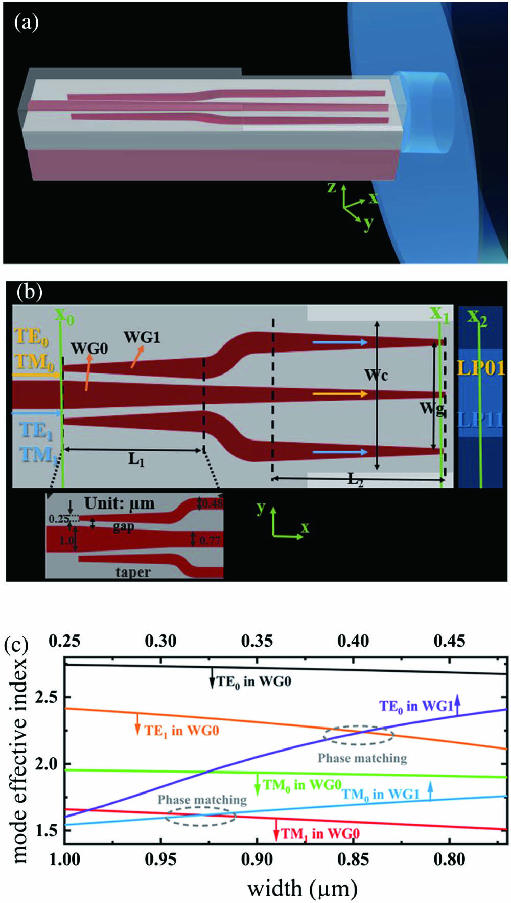
    Fig. 1. Schematics of DMEC coupling with dual-mode fiber in (a) 3D view and (b) top view; the silicon waveguides are in red, and the silicon oxide layer is in gray. The modes conversion process is also demonstrated. (c) Effective refractive index of the modes in each waveguide (WG0/WG1) of the mode-evolution counter-taper with tapering width from 1 µm/0.25 µm to 0.77 µm/0.48 µm.
    (a) Mode conversion loss for the input TE0, TM0, TE1, and TM1 modes, respectively, (b) transmission loss for the TE0 and TM0 modes in inverse taper (L2), and (c) wavelength dependence of the transmission from ‘x0’–‘x1’.
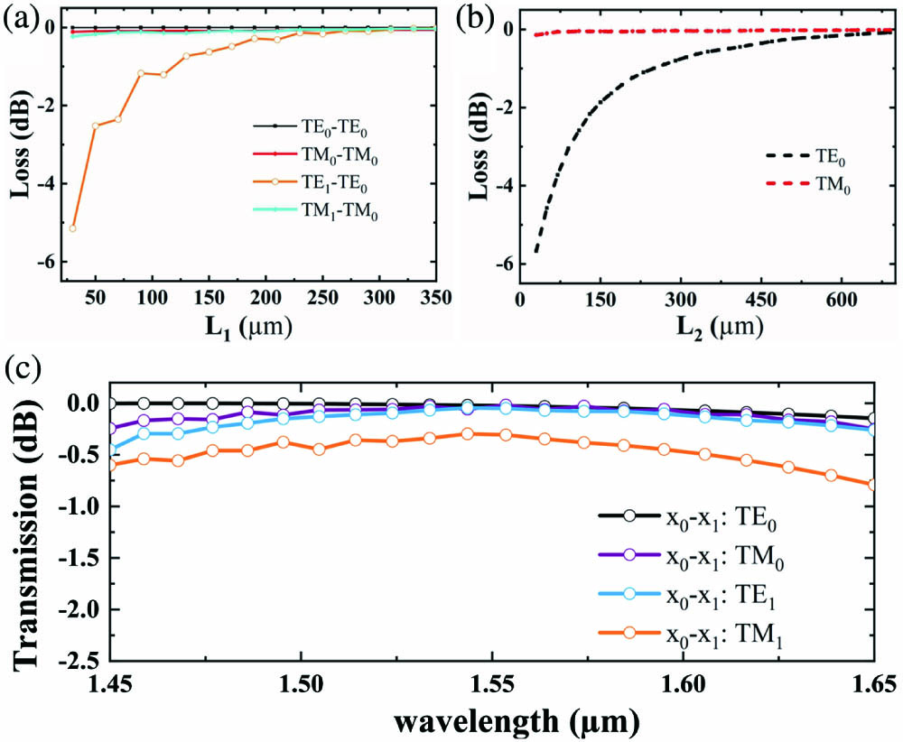
    Fig. 2. (a) Mode conversion loss for the input TE0, TM0, TE1, and TM1 modes, respectively, (b) transmission loss for the TE0 and TM0 modes in inverse taper (L2), and (c) wavelength dependence of the transmission from ‘x0’–‘x1’.
    Cross-sectional schematics of the edge coupling area: (a) x–y direction; (b) y–z direction.
    Fig. 3. Cross-sectional schematics of the edge coupling area: (a) xy direction; (b) yz direction.
    (a) Simulated overlap integral of mode field between the FMF and SiO2 cladding, (b) simulated coupling loss for different Wg, (c) spatial mode coupling (from ‘x1’–‘x2’), and (d) the lateral alignment tolerance of coupling efficiency (CE) for spatial mode coupling.
    Fig. 4. (a) Simulated overlap integral of mode field between the FMF and SiO2 cladding, (b) simulated coupling loss for different Wg, (c) spatial mode coupling (from ‘x1’–‘x2’), and (d) the lateral alignment tolerance of coupling efficiency (CE) for spatial mode coupling.
    (a) Total CE and (b) crosstalk of the FMEC in the span of 200 nm.
    Fig. 5. (a) Total CE and (b) crosstalk of the FMEC in the span of 200 nm.
    Simulated electrical field mode profiles of (a) TE0, (b) TM0, (c) TE1, and (d) TM1 modes at position ‘x0’ in Fig. 1(b); transmission profiles of the input (e) TE0, (f) TM0, (g) TE1, and (h) TM1 modes; mode profiles of the (i) TE0, (j) TM0, (k) TE1, and (l) TM1 modes in the SiO2 waveguide; mode profiles of (m) LP01,x, (n) LP01,y, (o) LP11a,x, and (p) LP11a,y modes supported in FMF.
    Fig. 6. Simulated electrical field mode profiles of (a) TE0, (b) TM0, (c) TE1, and (d) TM1 modes at position ‘x0’ in Fig. 1(b); transmission profiles of the input (e) TE0, (f) TM0, (g) TE1, and (h) TM1 modes; mode profiles of the (i) TE0, (j) TM0, (k) TE1, and (l) TM1 modes in the SiO2 waveguide; mode profiles of (m) LP01,x, (n) LP01,y, (o) LP11a,x, and (p) LP11a,y modes supported in FMF.
    Fabrication tolerance to deviation (a) of the waveguide width and thickness for TE1 input mode, (b) of the waveguide width and thickness for TM1 input mode, (c) of the tip width.
    Fig. 7. Fabrication tolerance to deviation (a) of the waveguide width and thickness for TE1 input mode, (b) of the waveguide width and thickness for TM1 input mode, (c) of the tip width.
    Ref.Number of ModesCompatible with CMOSCoupling Loss (dB)Evaluation Method
    [10]2YesTE0LP01:10.11Numerical
    2020TE1LP11:8.8
    [15]4NoLP01:8.8Experimental
    2017LP11a:9.0
    LP11b:9.6
    LP21a:9.9
    [17]1YesTE1LP11:3Numerical
    2017TE1LP11:5.5Experimental
    [16]4NoNo data/
    2020
    This work4YesTE0LP01,x:4.1Numerical
    TM0LP01,y:5.1
    TE1LP11a,x:2.1
    TM1LP11a,y:2.9
    Table 1. Comparison of the Reported Multimode Edge Coupler and Coupler Proposed in This Work
    Junbo Zhu, Haiyang Huang, Yingxuan Zhao, Yang Li, Zhen Sheng, Fuwan Gan. Efficient silicon integrated four-mode edge coupler for few-mode fiber coupling[J]. Chinese Optics Letters, 2022, 20(1): 011302
    Download Citation