• Photonics Research
  • Vol. 7, Issue 8, 875 (2019)
Yingfei Pang1,2,3, Axiu Cao1, Jiazhou Wang1, Hui Pang1..., Wei Yan1, Xiangdong Wu2, Lifang Shi1,4,* and Qiling Deng1,5,*|Show fewer author(s)
Author Affiliations
  • 1Institute of Optics and Electronics, Chinese Academy of Sciences, Chengdu 610209, China
  • 2School of Mechanical Engineering, Southwest Jiaotong University, Chengdu 610031, China
  • 3University of Chinese Academy of Sciences, Beijing 100049, China
  • 4e-mail: shilifang@ioe.ac.cn
  • 5e-mail: dengqiling@ioe.ac.cn
  • show less
    DOI: 10.1364/PRJ.7.000875 Cite this Article Set citation alerts
    Yingfei Pang, Axiu Cao, Jiazhou Wang, Hui Pang, Wei Yan, Xiangdong Wu, Lifang Shi, Qiling Deng, "Design and experimental verification of a monolithic complete-light modulator based on birefringent materials," Photonics Res. 7, 875 (2019) Copy Citation Text show less
    Example of a light field containing four regions as divided by the purple dotted lines. Distributions of the light field parameters are: (a) amplitude A(x,y), (b) polarization θ(x,y), (c) common phase φ(x,y), (d) phase differience δ(x,y), (e) amplitude Ao(x,y) of Eo(x,y), (f) amplitude Ae(x,y) of Ee(x,y), (g) phase φo(x,y) of Eo(x,y), and (h) phase φe(x,y) of Ee(x,y).
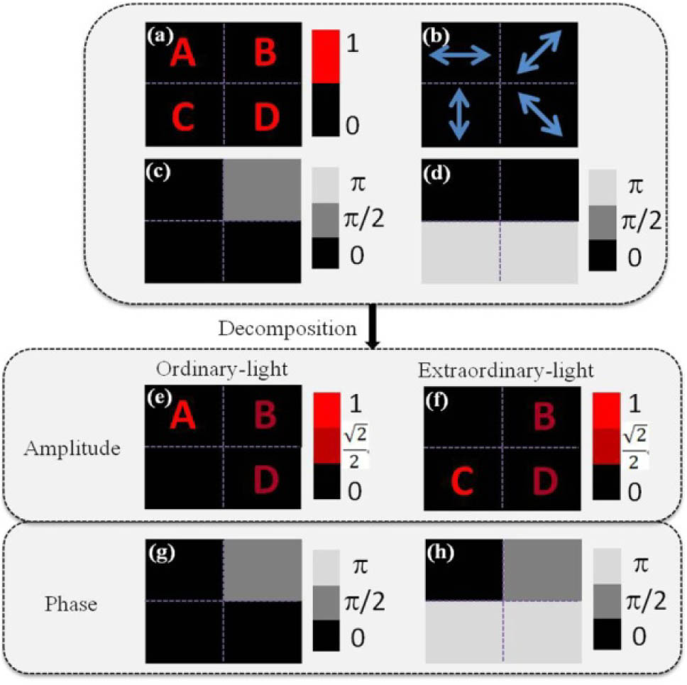
    Fig. 1. Example of a light field containing four regions as divided by the purple dotted lines. Distributions of the light field parameters are: (a) amplitude A(x,y), (b) polarization θ(x,y), (c) common phase φ(x,y), (d) phase differience δ(x,y), (e) amplitude Ao(x,y) of Eo(x,y), (f) amplitude Ae(x,y) of Ee(x,y), (g) phase φo(x,y) of Eo(x,y), and (h) phase φe(x,y) of Ee(x,y).
    Flow chart of the modified GS algorithm with both amplitude and phase limits.
    Fig. 2. Flow chart of the modified GS algorithm with both amplitude and phase limits.
    Parameters of the light field in the four regions: (a) intensity I(x,y), (b) linear polarization θ=0°, 45°, 90° and 135°, (c) common phase φ(x,y), and (d) phase differience δ(x,y).
    Fig. 3. Parameters of the light field in the four regions: (a) intensity I(x,y), (b) linear polarization θ=0°, 45°, 90° and 135°, (c) common phase φ(x,y), and (d) phase differience δ(x,y).
    Relief depth distribution of the MCLM that has 16 levels. The depth difference between adjacent levels is 0.13 μm.
    Fig. 4. Relief depth distribution of the MCLM that has 16 levels. The depth difference between adjacent levels is 0.13 μm.
    Simulation results: (a) without polarizer; with polarizer oriented at (b) 0°, (c) 45°, (d) 90°, and (e) 135°.
    Fig. 5. Simulation results: (a) without polarizer; with polarizer oriented at (b) 0°, (c) 45°, (d) 90°, and (e) 135°.
    Fabrication process of the MCLM: (a) the first etching with etching depth of 130 nm, (b) the second etching with etching depth of 260 nm, (c) the third etching with etching depth of 520 nm, and (d) the fourth etching with etching depth of 1024 nm.
    Fig. 6. Fabrication process of the MCLM: (a) the first etching with etching depth of 130 nm, (b) the second etching with etching depth of 260 nm, (c) the third etching with etching depth of 520 nm, and (d) the fourth etching with etching depth of 1024 nm.
    Four masks used in the MCLM fabrication process: (a) mask one, (b) mask two, (c) mask three, and (d) mask four.
    Fig. 7. Four masks used in the MCLM fabrication process: (a) mask one, (b) mask two, (c) mask three, and (d) mask four.
    (a) Fabricated MCLM. (b) Structure of the MCLM observed under microscope.
    Fig. 8. (a) Fabricated MCLM. (b) Structure of the MCLM observed under microscope.
    Experimental setup and light beam path for testing the MCLM performance.
    Fig. 9. Experimental setup and light beam path for testing the MCLM performance.
    Experimental results. The desired intensity pattern is received by a CCD. (a) No polarizer analyzer. In (b)–(e), the polarizer analyzer was oriented at 0°, 45°, 90°, and 135°, respectively.
    Fig. 10. Experimental results. The desired intensity pattern is received by a CCD. (a) No polarizer analyzer. In (b)–(e), the polarizer analyzer was oriented at 0°, 45°, 90°, and 135°, respectively.
    Yingfei Pang, Axiu Cao, Jiazhou Wang, Hui Pang, Wei Yan, Xiangdong Wu, Lifang Shi, Qiling Deng, "Design and experimental verification of a monolithic complete-light modulator based on birefringent materials," Photonics Res. 7, 875 (2019)
    Download Citation