
Brian Slovick, Josh Hellhake. Inverse design of invisibility cloaks using the optical theorem[J]. Photonics Research, 2022, 10(4): 974
- Photonics Research
- Vol. 10, Issue 4, 974 (2022)
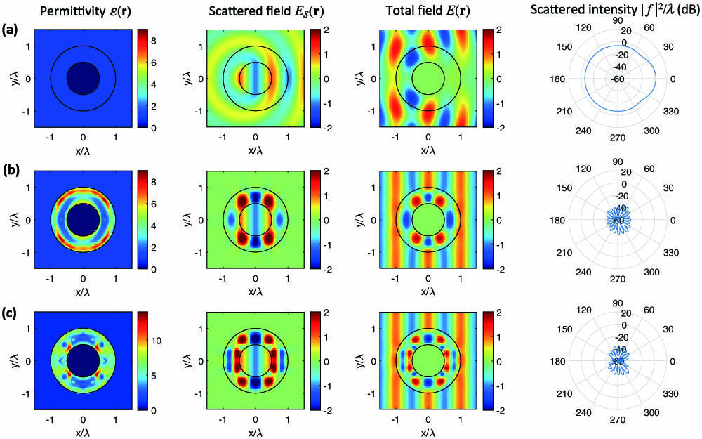
Fig. 1. Relative permittivity, scattered fields, total fields, and scattered intensity for a 0.5 λ 0.5 λ ϵ shell = 3 0.5 λ ϵ shell = 5

Fig. 2. Relative permittivity, scattered fields, total fields, and scattered intensity for a 0.5 λ 0.25 λ ϵ shell = 3 0.25 λ ϵ shell = 5
Fig. 3. Relative permittivity, scattered fields, total fields, and scattered intensity for an elliptical metal rod with 0.8 λ 0.4 λ 0.2 λ ϵ shell = 3 0.2 λ ϵ shell = 5
Fig. 4. Cross section of the uncloaked structure in Fig. 1 (a) and the optimized cloak in Fig. 1 (b) as a function of (a) wavelength and (b) angle of incidence.

Set citation alerts for the article
Please enter your email address
© Copyright 2018-2021 | Chinese Laser Press. All Rights Reserved 沪ICP备15018463号-20